Eureka AIR delivers breakthrough ideas for toughest innovation challenges, trusted by R&D personnel around the world.

Disc seat for thermal switch

Active Publication Date: 2009-03-26
HONEYWELL INT INC
View PDF16 Cites 1 Cited by
  • Summary
  • Abstract
  • Description
  • Claims
  • Application Information

AI Technical Summary

Benefits of technology

[0007]The present invention generally relates to a thermal switch of the bimetallic snap action type having a bimetallic disc. More specifically, the thermal switch includes a disc seat that cooperates wit

Problems solved by technology

In addition, the thermal switches must often meet stringent temperature set point or threshold drift requirements over an operational life of typically twenty or more years.
Consequently, repeated actuation of the bimetallic disc has been known to cause an undesirable amount of wear to the disc, the striker pin, the case, or some combination of each.
The amount of wear may become undesirable if it is sufficient to cause the set point temperature to “drift.” For example, the amount of wear may be undesirable if it causes a significant change in temperature in either the opening or the closing of the electrical circuit.

Method used


Image

  • Disc seat for thermal switch
  • Disc seat for thermal switch
  • Disc seat for thermal switch

Examples


Embodiment Construction

[0018]In the following description, certain specific details are set forth in order to provide a thorough understanding of various embodiments of the invention. However, one skilled in the art will understand that the invention may be practiced without these details or with various combinations of these details. In other instances, well-known structures and methods associated with thermal switches, armatures, electrical contacts or terminals, to include the operation thereof may not be shown or described in detail to avoid unnecessarily obscuring descriptions of the embodiments of the invention.

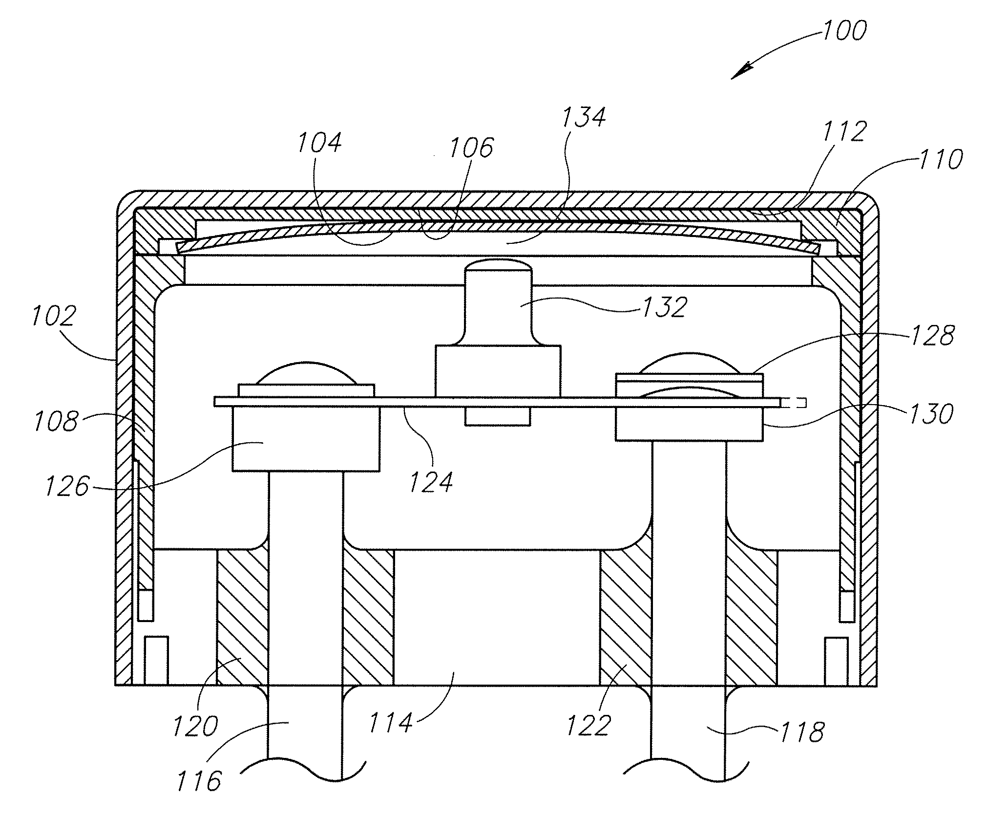
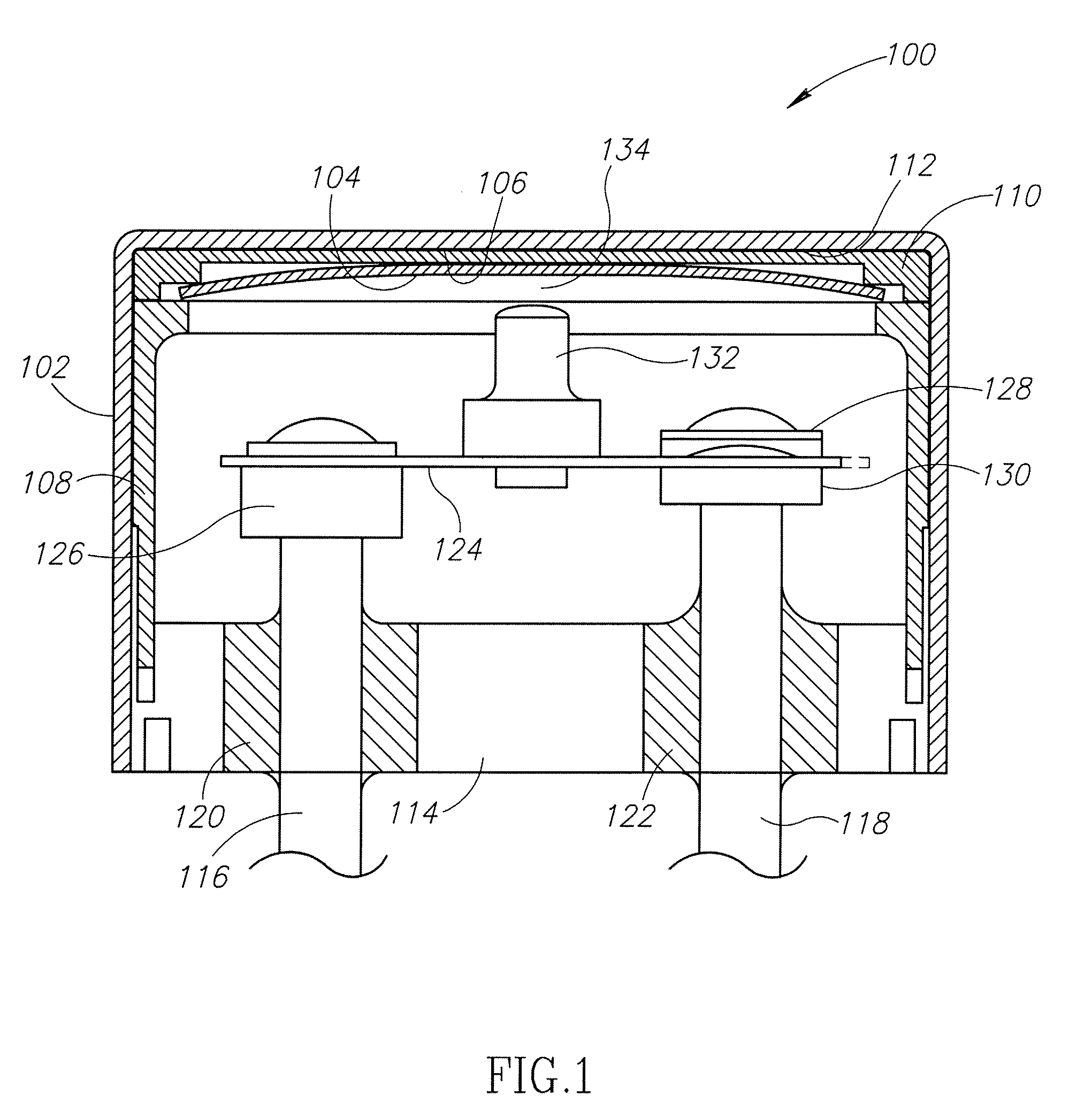
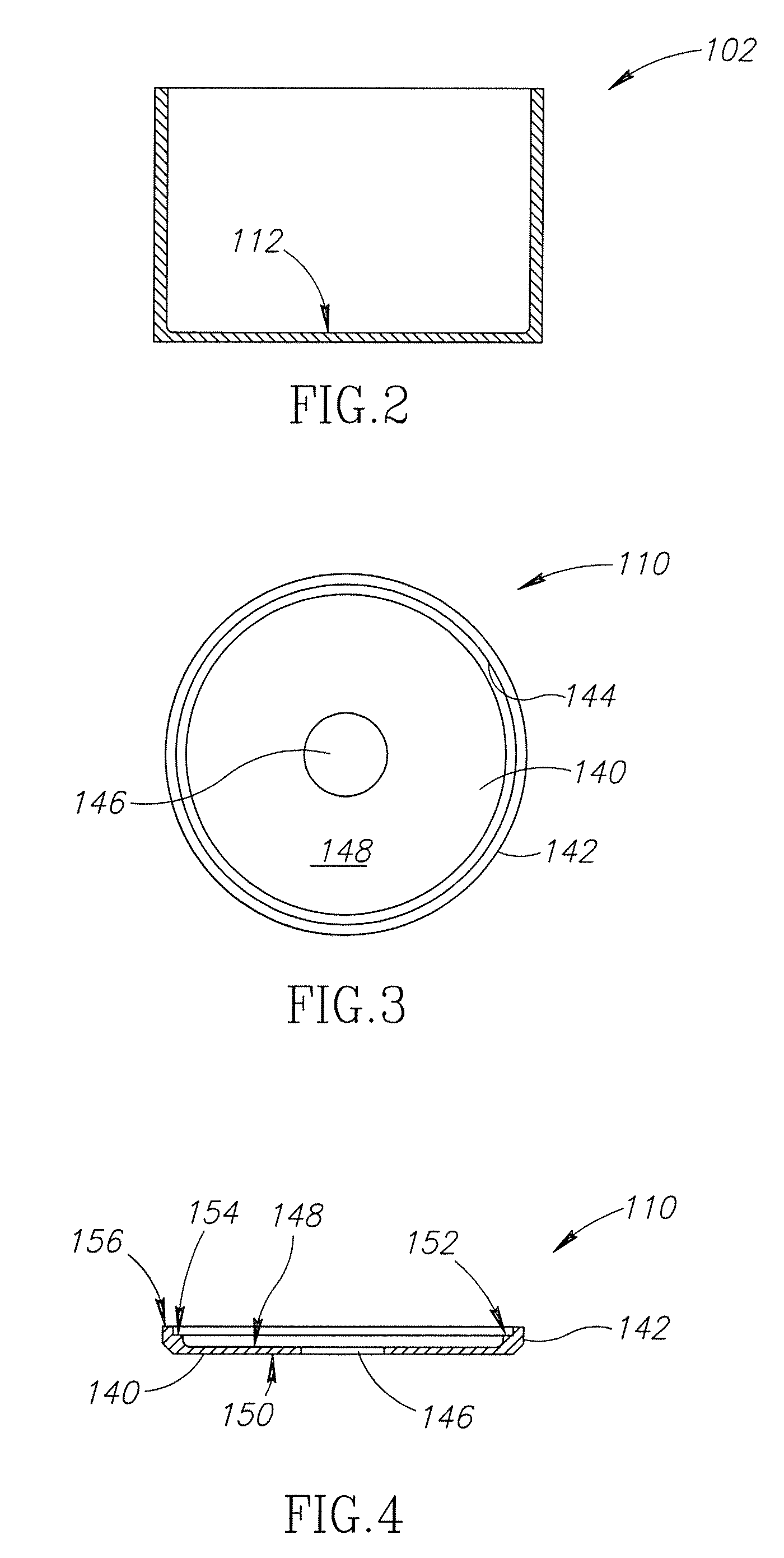
[0019]The following description is generally directed to a thermal switch having a low abrasive and wear resistant disc seat for holding a bimetallic disc. The disc seat includes a disc body with a flange extending from a periphery of the disc body. A centrally-located through opening may be located in the disc body to prevent warping of the disc body during its manufacture and to help reliev...


PUM


Abstract

A thermal switch includes a low abrasive and wear resistant disc seat for holding a bimetallic disc. The disc seat includes a disc body with a flange extending from a periphery of the disc body. A centralized through opening may be located in the disc body to prevent warping of the disc body during its manufacture. In addition, the disc seat may be made from brass where at least a first surface of the disc body is plated with Teflon Electroless Nickel, which may take the form of sub-micron particles of polytetrafluoroethylene with auto-catalytically applied nickel.

Description

BACKGROUND OF THE INVENTION[0001]Thermostatic switches, commonly referred to as thermal switches, are engineered for use in high reliability applications such as Space Science Satellites, Defense Satellites, Commercial Satellites, Manned Space Flight Programs and High-Value Terrestrial Applications. The operating and life specifications for thermal switches often require that the switches exhibit a high reliability while operating under extreme conditions such as within Space and Launch Vehicles. In addition, the thermal switches must often meet stringent temperature set point or threshold drift requirements over an operational life of typically twenty or more years.[0002]The conventional thermal switches currently used for the above-identified applications may be bimetallic snap action type. A bimetallic disc is made of two dissimilar metals, where one metal has a low coefficient of thermal expansion and the other metal has a higher coefficient of thermal expansion. The bi-metal ma...

Claims


Application Information

Patent Timeline
IPC IPC(8): H01H37/00
CPCH01H2037/549H01H37/54
Inventor SCOTT, BYRON G.DAVIS, GEORGE D.EHRET, JOHN F.
Owner HONEYWELL INT INC
Why Eureka
Eureka Blog
Learn More