Detection and ranging appartus and detection and ranging method

a technology of detection and ranging apparatus, applied in the direction of measuring devices, using reradiation, instruments, etc., can solve the problems of reducing the detection range, adverse effects, affecting the accuracy of measurement, and reducing the number of antenna elements without compromising reception power, so as to improve the effective aperture of the sensor array, eliminate adverse effects, and improve the effect of detection rang

Inactive Publication Date: 2009-03-26
FUJITSU LTD +1
View PDF19 Cites 102 Cited by
  • Summary
  • Abstract
  • Description
  • Claims
  • Application Information

AI Technical Summary

Benefits of technology

[0012]Accordingly, it is an object of the present invention to provide a detection and ranging apparatus that uses a plurality of transmitting sensors in order to enlarge the effective aperture of a sensor array having a plurality of sensor elements, wherein provisions are made to eliminate the adverse effects associated with the time division switching and thereby achieve a high-accuracy measurement.

Problems solved by technology

However, in the case of a radar apparatus such as an automotive radar where severe constraints are imposed on the mounting dimensions of the antenna, it has been difficult to increase the number of antenna elements without compromising reception power.
However, switching from one antenna to another using a switch involves adverse effects such as degradation in signal and reduction in detection range.
Furthermore, since it does not follow that the waves transmitted out from the plurality of transmitting antennas and returned by reflection are received simultaneously by the plurality of receiving antennas, there arises the problem that a time shift and a phase shift occur.
This problem can be alleviated by increasing the switching speed, but there is naturally a limit to it.

Method used


Image

  • Detection and ranging appartus and detection and ranging method
  • Detection and ranging appartus and detection and ranging method
  • Detection and ranging appartus and detection and ranging method

Examples


Embodiment Construction

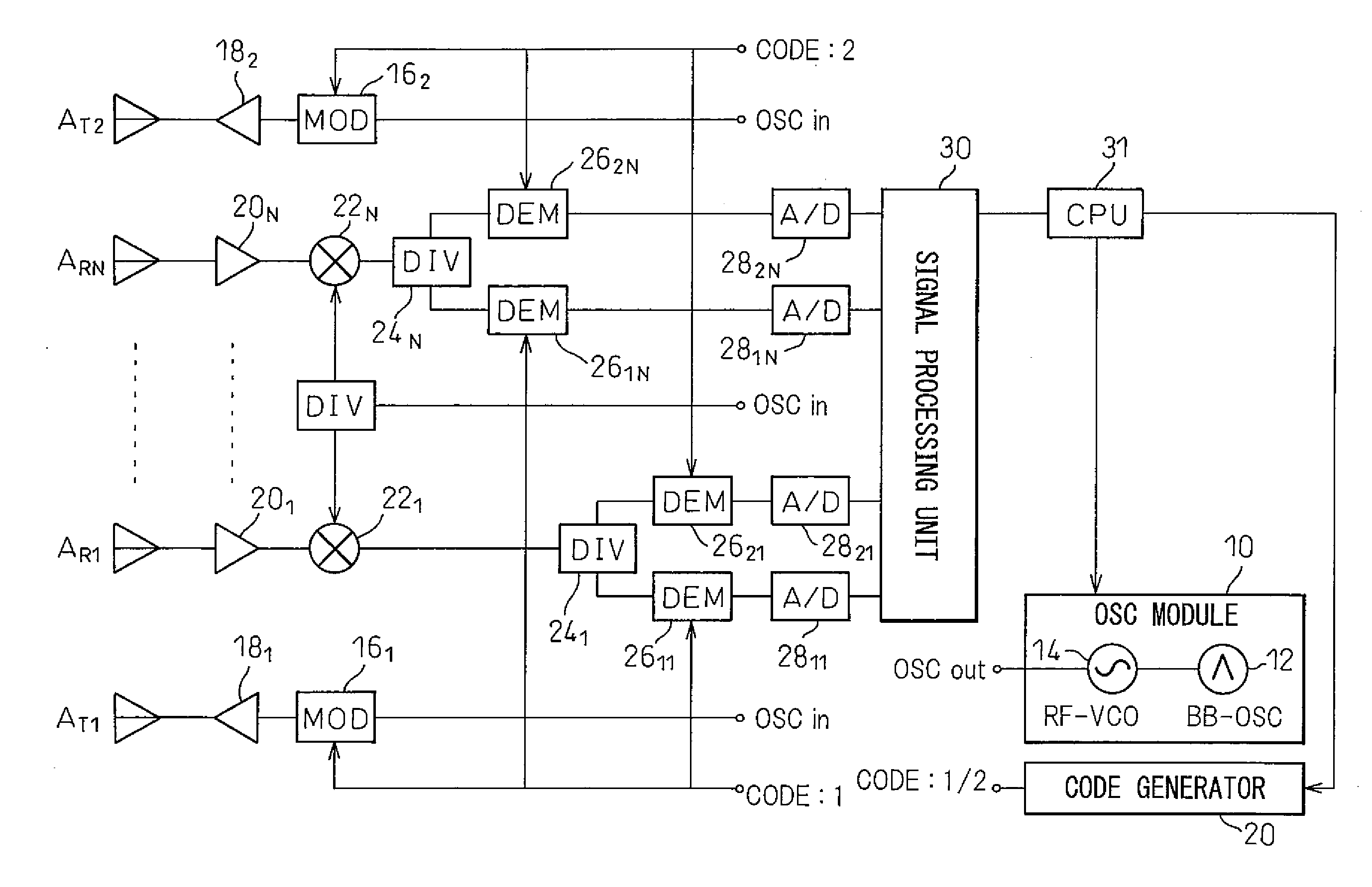
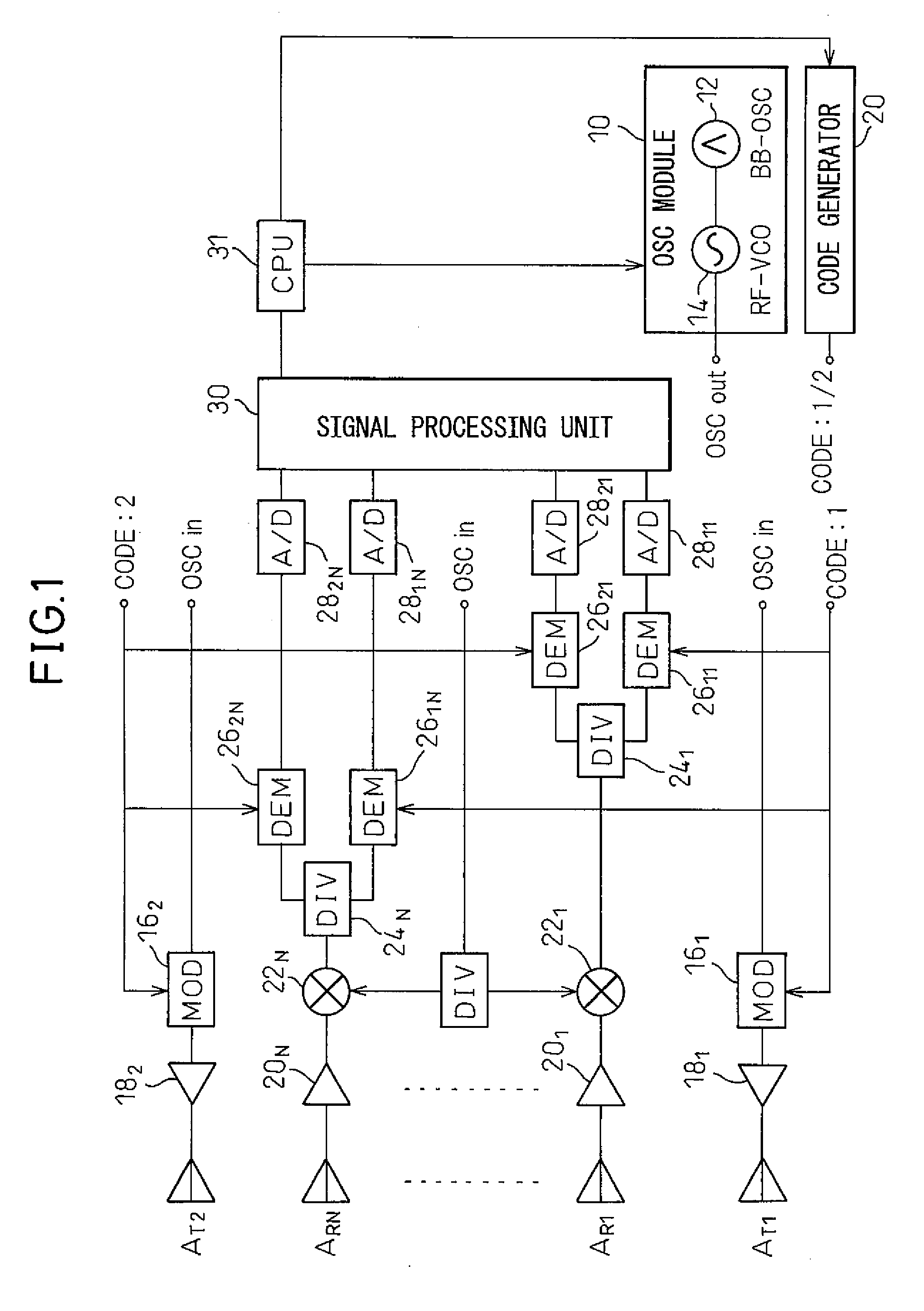
[0022]FIG. 1 shows the configuration of a radar apparatus according to an embodiment. The example shown in FIG. 1, similarly to the one shown in JP 2006-98181A, uses a receiving array antenna comprising N antenna elements AR1 to ARN and a transmitting array antenna comprising two (M=2) antenna elements AT1 and AT2 arranged on both sides of the receiving array antenna.

[0023]An oscillator module 10 includes an oscillator 12 for generating a baseband signal such as a triangular wave and a voltage-controlled RF (Radio Frequency) oscillator 14 whose frequency is controlled by the output of the oscillator 12, and generates a transmitter wave frequency-modulated by the triangular wave. A code generator 20 generates mutually orthogonal two PN codes 1 and 2. The transmitter wave frequency-modulated by the triangular wave is directly spread by binary phase-shift keying (BPSK) using the PN codes 1 and 2 in modulators 161 and 162, and the resulting transmitter waves are fed via power amplifiers...


PUM


Abstract

In a detection and ranging apparatus that performs direction-of-arrival estimation using a sensor array and that enlarges an effective aperture using a plurality of transmitting sensors, adverse effects associated with time division switching are eliminated, achieving high-accuracy measurement. A transmitter wave is spread in modulators by using mutually orthogonal codes, and the resulting transmitter waves are radiated from two transmitting sensors. Signals received by receiving sensors are each split by a splitter into two parts, which are then respectively despread in a demodulator by using the same codes as those used in the transmitter.

Description

BACKGROUND OF THE INVENTION[0001]1. Field of the Invention[0002]The present invention relates to a detection and ranging apparatus and detection and ranging method having a function for estimating the direction of arrival of a signal by using a sensor array and a direction-of-arrival estimation method.[0003]2. Description of the Related Art[0004]As an example of such a detection and ranging apparatus, consider a radar apparatus capable of estimating all three quantities, i.e., relative distance, relative velocity, and angular direction of a target. In a radar, a sensor refers to an antenna. FM-CW radar is a type of radar that projects forward a transmitter wave frequency-modulated by a triangular wave or the like, and receives a reflected wave from a target, mixes it in a mixer with a portion of the transmitted signal to obtain a baseband signal containing information on the target, and calculates the distance and relative velocity of the target from the baseband signal, and this ty...

Claims


Application Information

Patent Timeline
Patent Type & Authority Applications(United States)
IPC IPC(8): G01S13/08G01S5/02G01S13/28G01S13/34
CPCG01S7/032G01S13/325G01S2013/0254G01S13/87G01S13/931G01S13/34
Inventor SHIRAKAWA, KAZUOOHGUCHI, KATSUYUKIKONDO, YASUYUKI
Owner FUJITSU LTD
Why Eureka
Try Eureka