Fluidic electrostatic energy harvester

a technology of electrostatic energy harvester and flux, which is applied in the direction of mechanically variable capacitor details, variable capacitors, transportation and packaging, etc., can solve the problems of large system energy harvesting of relatively large amounts, inability to meet the requirements of the inertial mass system, and large energy loss of large systems

Inactive Publication Date: 2009-03-26
INFINEON TECH AG
View PDF9 Cites 34 Cited by
  • Summary
  • Abstract
  • Description
  • Claims
  • Application Information

AI Technical Summary

Benefits of technology

[0005]The following presents a simplified summary in order to provide a basic understanding of one or more aspects of the invention. This summary presents one or more concepts of the invention in a simplified form as a prelude to the more detaile

Problems solved by technology

These large systems harvest relatively large amounts of energy.
There are two main problems associated with these devices.
First, these movable mechanical parts are known to be a major source of failure in these devices due to crack formation, bea

Method used


Image

  • Fluidic electrostatic energy harvester
  • Fluidic electrostatic energy harvester
  • Fluidic electrostatic energy harvester

Examples


Embodiment Construction

[0022]The present invention will now be described with reference to the attached drawing figures, wherein like reference numerals are used to refer to like elements throughout, and wherein the illustrated structures and devices are not necessarily drawn to scale.

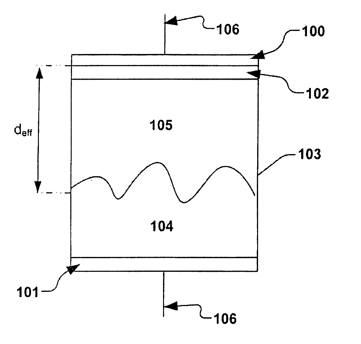
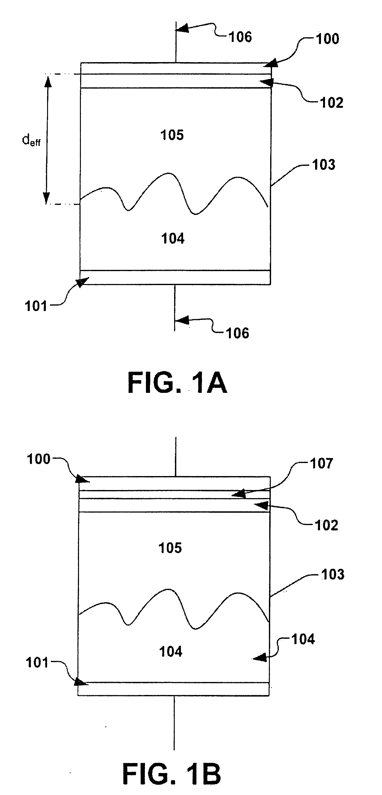
[0023]Referring now to FIG. 1A, the basic structure of the variable capacitor comprises two electrodes 100 and 101, separated by an insulating layer 102 and an enclosed chamber 103. The enclosed chamber can be fabricated of various materials and of differing size according to various embodiments. Within the enclosed chamber 103 is contained a conductive material that can change its position freely when a force is applied thereto (e.g., gravity, acceleration, centrifugal motion, etc.). In one embodiment, the force applied to the conductive material will result in a change of position or orientation of the variable capacitor. The conductive material, for example, in one embodiment could be a combination of fluid 104 and gas 10...


PUM


Abstract

One embodiment of the present invention relates to a variable capacitor that operates without moving mechanical parts. In this capacitor electrically conductive electrodes are separated by an enclosed chamber filled with an electrically conductive material. The electrically conductive material can freely vary its position within the chamber. The capacitance of the device will vary as position of the conductive material changes due to external mechanical motion (ex: rotation vibration, etc.) of the device. Other embodiments of this device are also disclosed.

Description

FIELD OF INVENTION[0001]The present invention relates generally to a variable capacitor intended for use within an energy harvesting system. The energy harvesting system can further be used to power a tire sensor system in one embodiment.BACKGROUND OF THE INVENTION[0002]Energy harvesting is a process of taking energy from a chaotic system and converting it to a form of energy that can either be stored or used in a controlled manner. Energy harvesting is well known in forms such as hydroelectric turbines, solar cells, wind turbines, and other similar systems that have gained wide public exposure. These large systems harvest relatively large amounts of energy. Recently, science has begun to look for smaller energy harvesting systems. As the power requirements of small electronic devices have decreased, attempts have been made to harvest energy on a smaller scale and use that energy to power the devices.[0003]Many of these micro energy harvesting systems exploit mechanical energy and a...

Claims


Application Information

Patent Timeline
IPC IPC(8): H01G5/04
CPCB60C23/041H01G5/40H01G5/04H01G5/0132
Inventor LOHNDORF, MARKUSKVISTEROEY, TERJETHEUSS, HORSTBLIXHAVN, BJOERN
Owner INFINEON TECH AG
Why Eureka
Try Eureka