
Radiation image capturing apparatus

Active Publication Date: 2009-03-26
FUJIFILM CORP
View PDF3 Cites 4 Cited by
  • Summary
  • Abstract
  • Description
  • Claims
  • Application Information

AI Technical Summary

Benefits of technology

[0009]It is an object of the invention to provide a radiation image capturing apparatus that allows uniform cooling of a radiation detector even when constraints exist on the arrangement of the radiation detector.
[0011]According to the invention, the cooling medium flowing along the detection surface of the radiation detector from the front end side toward the rear end side of the housing cools the front end of the radiation detector and portions thereof in proximity to the front end. Thus, even if the radiation detector is arranged within the housing such that heat tends to accumulate at the front end side of the housing, the accumulated heat can be released efficiently, and thus uniform cooling of the entire detection surface of the radiation detector can be achieved.
[0013]The inlet port is preferably formed on both left and right sides of the housing and / or on an underside of the housing. In a mammography apparatus, for example, since the front surface of the housing faces toward the subject, whereas the subject's breast is placed on the upper surface, both surfaces are inadequate for introduction of the cooling medium. Therefore, in the present invention, the cooling medium is introduced into the housing from right and left sides and from the underside of the housing, thereby allowing the cooling medium to be introduced reliably into the housing.

Problems solved by technology

In many radiation image capturing apparatuses, however, the arrangement of the radiation detector within the image capturing unit is restricted for various reasons.
Consequently, a large size for the image capturing unit housing is not permitted, and the radiation detector must be contained within a small space.
Furthermore, since image capturing up to the base of the breast is required, the radiation detector must be located within the housing such that the distance between the radiation detector and the chest wall of the patient becomes suitably short during a mammography examination.
Such an arrangement causes insufficient heat to be released from the radiation detector.
This results in non-uniform cooling of the radiation detector, which in turn tends to reduce imaging accuracy.

Method used


Image

  • Radiation image capturing apparatus
  • Radiation image capturing apparatus
  • Radiation image capturing apparatus

Examples


Embodiment Construction

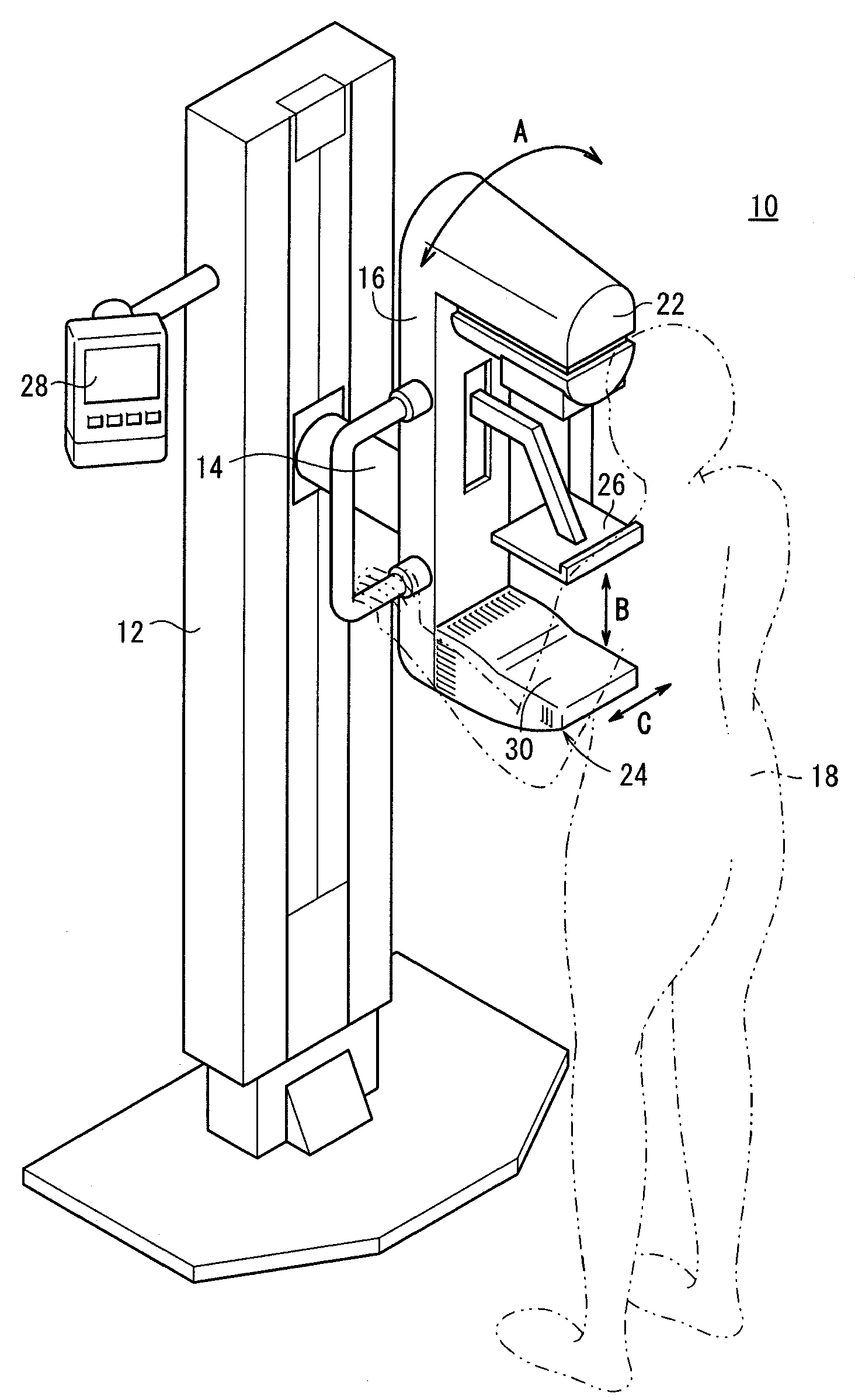
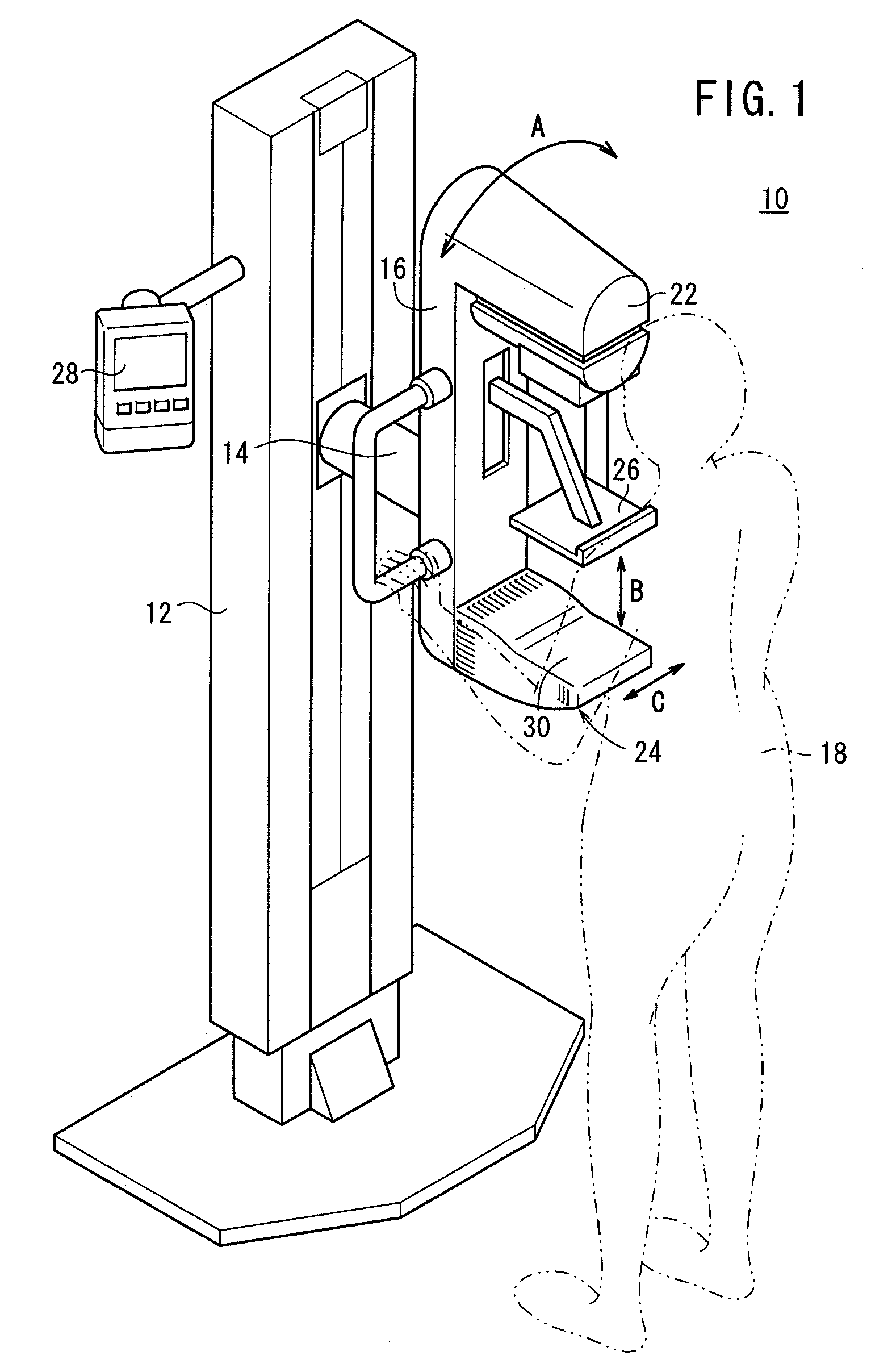
[0026]FIG. 1 shows a perspective view of an embodiment of a radiation image capturing apparatus according to the present invention, which is a mammography apparatus 10 for breast cancer screening or the like.

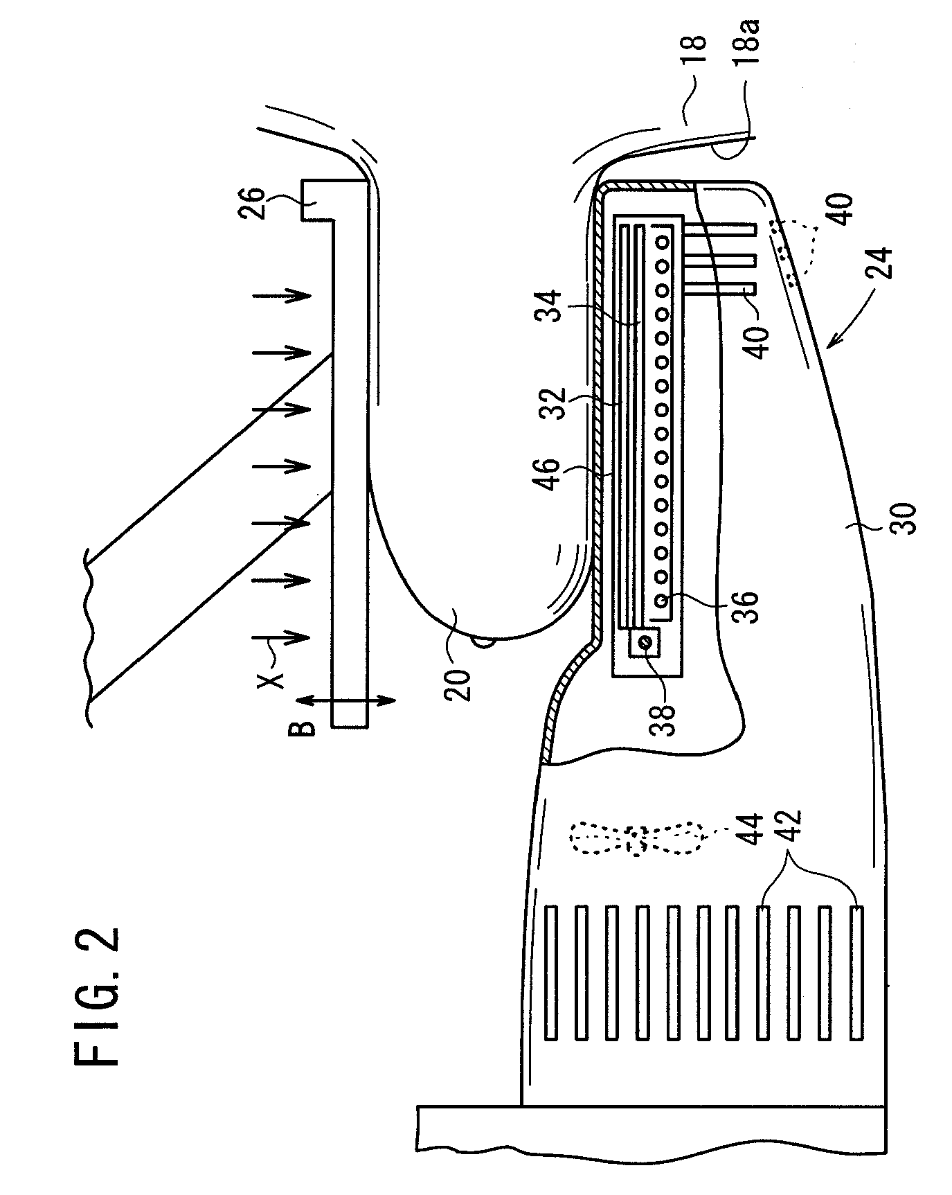
[0027]The mammography apparatus 10 includes an upstanding base 12, an arm 16 fixed to a pivot shaft 14 that is connected substantially centrally to the base 12, a radiation source housing unit 22 fixed to one end of the arm 16 and housing a radiation source (not shown) therein for applying radiation X or other recordable electromagnetic waves to a breast 20 (see FIG. 2), which constitutes a site of the subject 18 to be imaged, an image capturing base 24 fixed to the other end of the arm 16 in opposition to the radiation source housing unit 22, and a compression plate 26 for holding the breast 20 by compressing the breast 20 against the image capturing base 24.

[0028]The arm 16 holding the radiation source housing unit 22 and the image capturing base 24 can be rotated about the pi...


PUM


Abstract

An image capturing base that contains a radiation detector includes a housing having a slit serving as an air inlet port formed in the front end side of the housing, which is to be located adjacent to the chest wall of a subject, and a slit serving as an air outlet port formed in the rear end side of the housing adjacent to a pivot shaft. A fan forces air to flow into the housing through the slit, along a detection surface of the radiation detector in a direction from the front end side toward the rear end side, and out of the housing through the slit.

Description

BACKGROUND OF THE INVENTION[0001]1. Field of the Invention[0002]The present invention relates to a radiation image capturing apparatus that includes a radiation detector for detecting a radiation image of a subject and generating electrical signals representing the detected radiation image. More particularly, the present invention concerns a radiation image capturing apparatus that includes a mechanism for cooling the radiation detector.[0003]2. Description of the Related Art[0004]In a radiation image capturing apparatus, such as an X-ray breast image capturing apparatus (e.g., a mammography apparatus) or the like, a radiation image is generated by exposing a subject (patient) to radiation and recording the radiation in a radiation image recording unit (i.e., a radiation detector). The radiation image recording unit is thereafter scanned with reading light emitted from a reading light source, which is moved relative to the radiation image recording unit, in order to read out therefr...

Claims


Application Information

Patent Timeline
IPC IPC(8): A61B6/04
CPCA61B6/0414A61B6/502A61B6/4488
Inventor MIYAKO, KUNIAKINAKATA, HAJIMEHAKAMATA, KAZUOOHTA, YASUNORI
Owner FUJIFILM CORP
Features
  • Generate Ideas
  • Intellectual Property
  • Life Sciences
  • Materials
  • Tech Scout
  • Unparalleled Data Quality
  • Higher Quality Content
  • 60% Fewer Hallucinations
Learn More