

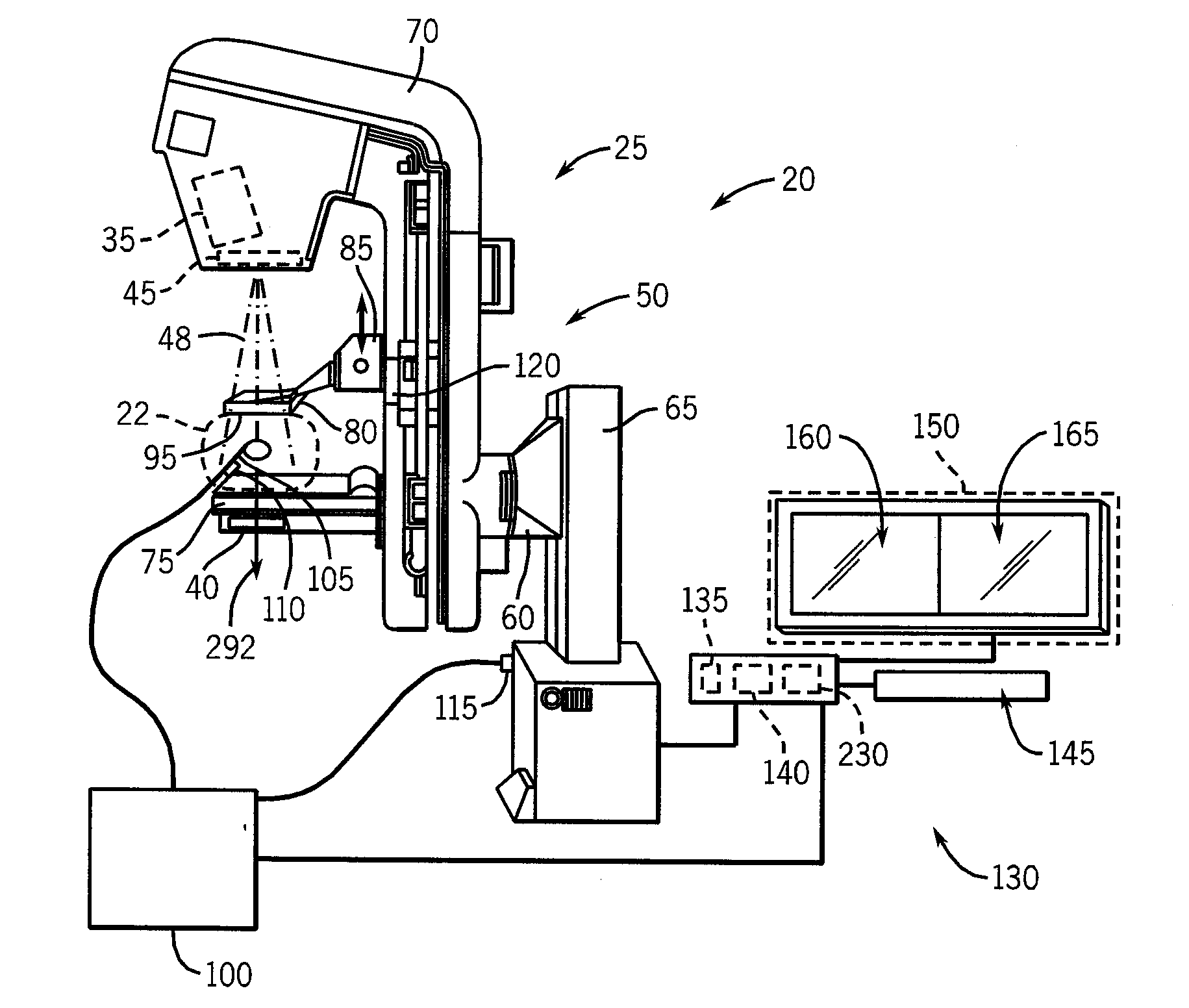
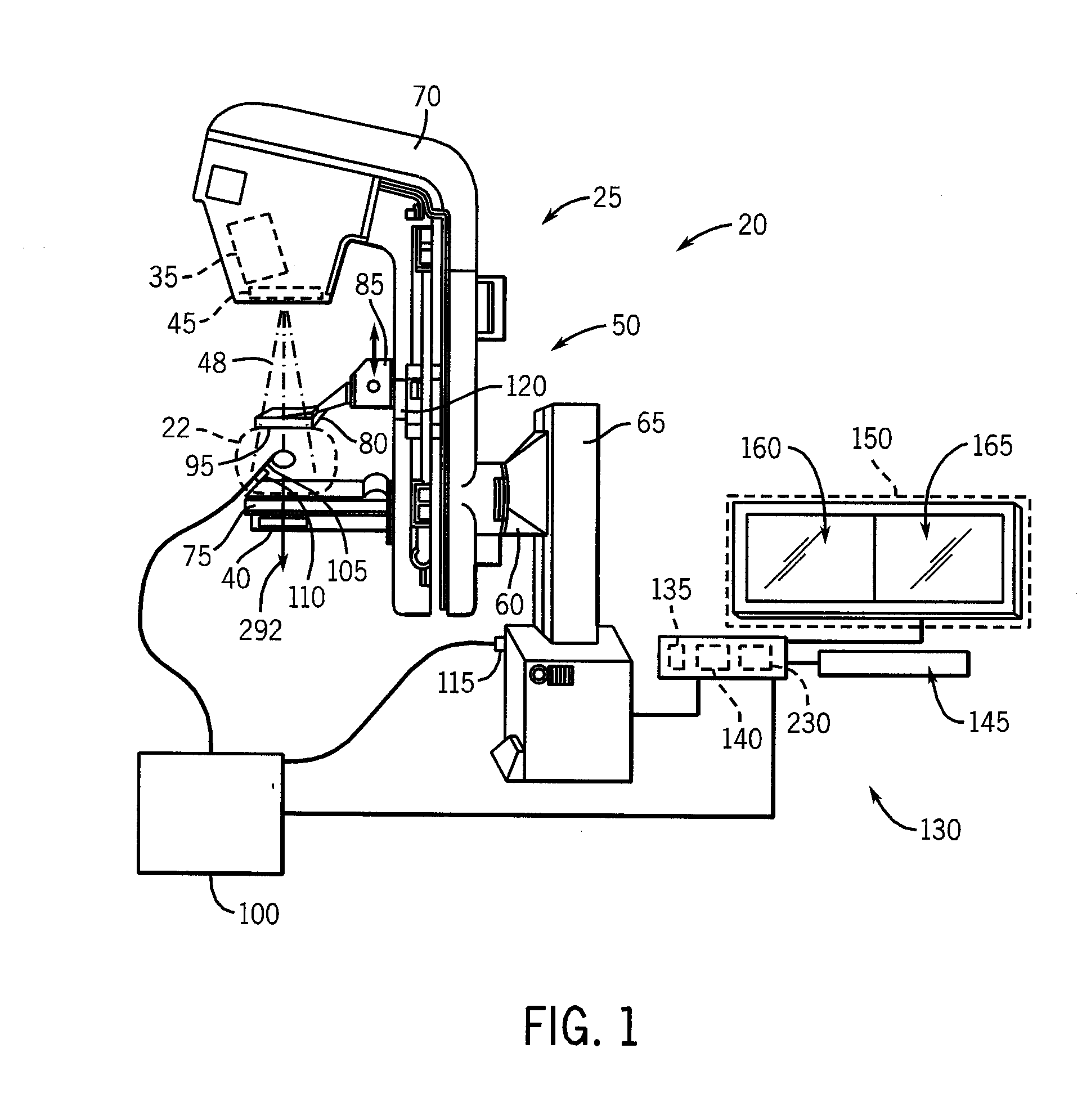
System and method to generate a selected visualization of a radiological image of an imaged subject
a radiological image and visualization technology, applied in the field of radiological imaging, can solve the problems of increasing the chances of false positive interpretation and false negative interpretation
- Summary
- Abstract
- Description
- Claims
- Application Information
AI Technical Summary
Benefits of technology
Problems solved by technology
Method used
Image

Examples
second embodiment
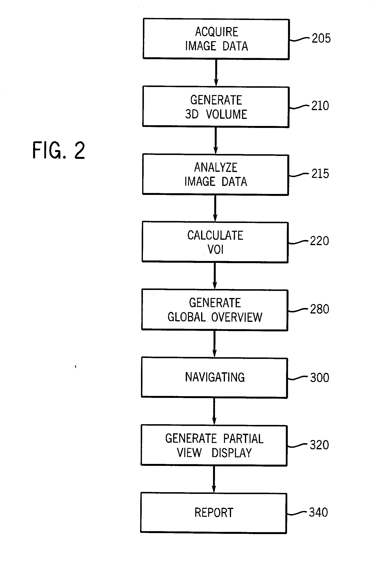
[0040]step 225 includes calculating or generating a mathematical model that defines a shape (e.g., ellipsoid, cylinder, sphere, etc. or combination thereof) of the bounding surface 226 that defines the VOI 228 identified in the three-dimensional, reconstructed volume 212 identified to include the suspect lesion. This embodiment of step 225 includes applying an algorithm to calculate a distribution of the image elements (e.g., pixels, voxels) identified to include a radiology sign or opacity of the suspect lesion, and then correlating the distribution of the image elements to a parametric shape and size as defined by the mathematical model to be the bounding surface 226 of the VOI 228 that at least envelopes the suspect lesion. The shape and size of the bounding surface 226 defined by the mathematical model can vary.
[0041]An embodiment of step 225 further includes comparing the bounding surface 226 to predefined constraint parameters (e.g., shape and size) of the suspect lesion, and ...
first embodiment
[0055]For example, step 300 can include receiving an instruction indicative or identifying the bounding surface or marker 226 at the volume 212 or the overview image 285 to be enlarged and illustrated in the second display window 165. This embodiment of step 300 includes receiving an instruction (e.g., click of a mouse device) so as to identify the marker or boundary surface 226 of the VOI 228 to be enlarged and simultaneously illustrated in the second viewport 165 along with the digital, three-dimensional reconstructed volume 212 illustrated in the first viewport 160. Similar to the first embodiment, the contrast or intensity level of the illustration marker or bounding surface 226 can be set to a maximum level so as to further highlight or delineate relative to the image elements that constitute the volume 212 or the overview image 285.
[0056]According to another embodiment, step 300 includes receiving an instruction (e.g., click of a mouse device 145 at the bounding surface or mar...
PUM
 Abstract
Description
Claims
Application Information