Scheduling method and system for optical burst switched networks

a technology of optical burst switching and scheduling method, applied in the field of optical communication network, can solve the problem of not being able to schedule a particular protocol

Inactive Publication Date: 2009-03-26
RES TRIANGLE INST
View PDF2 Cites 30 Cited by
  • Summary
  • Abstract
  • Description
  • Claims
  • Application Information

AI Technical Summary

Problems solved by technology

Unfortunately, while OBS has achieved some favor with the telecommunications industry, such is not the case for any particular scheduling protocol.

Method used


Image

  • Scheduling method and system for optical burst switched networks
  • Scheduling method and system for optical burst switched networks
  • Scheduling method and system for optical burst switched networks

Examples


Embodiment Construction

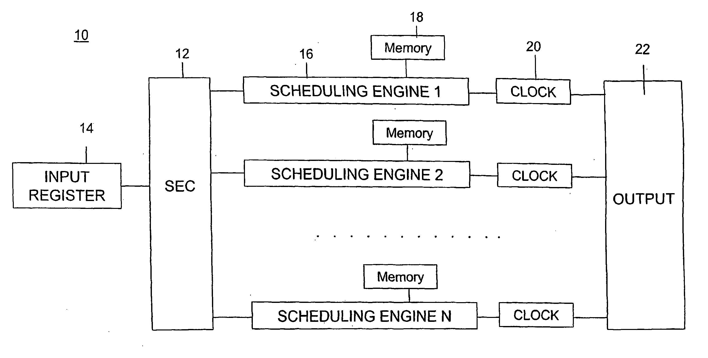
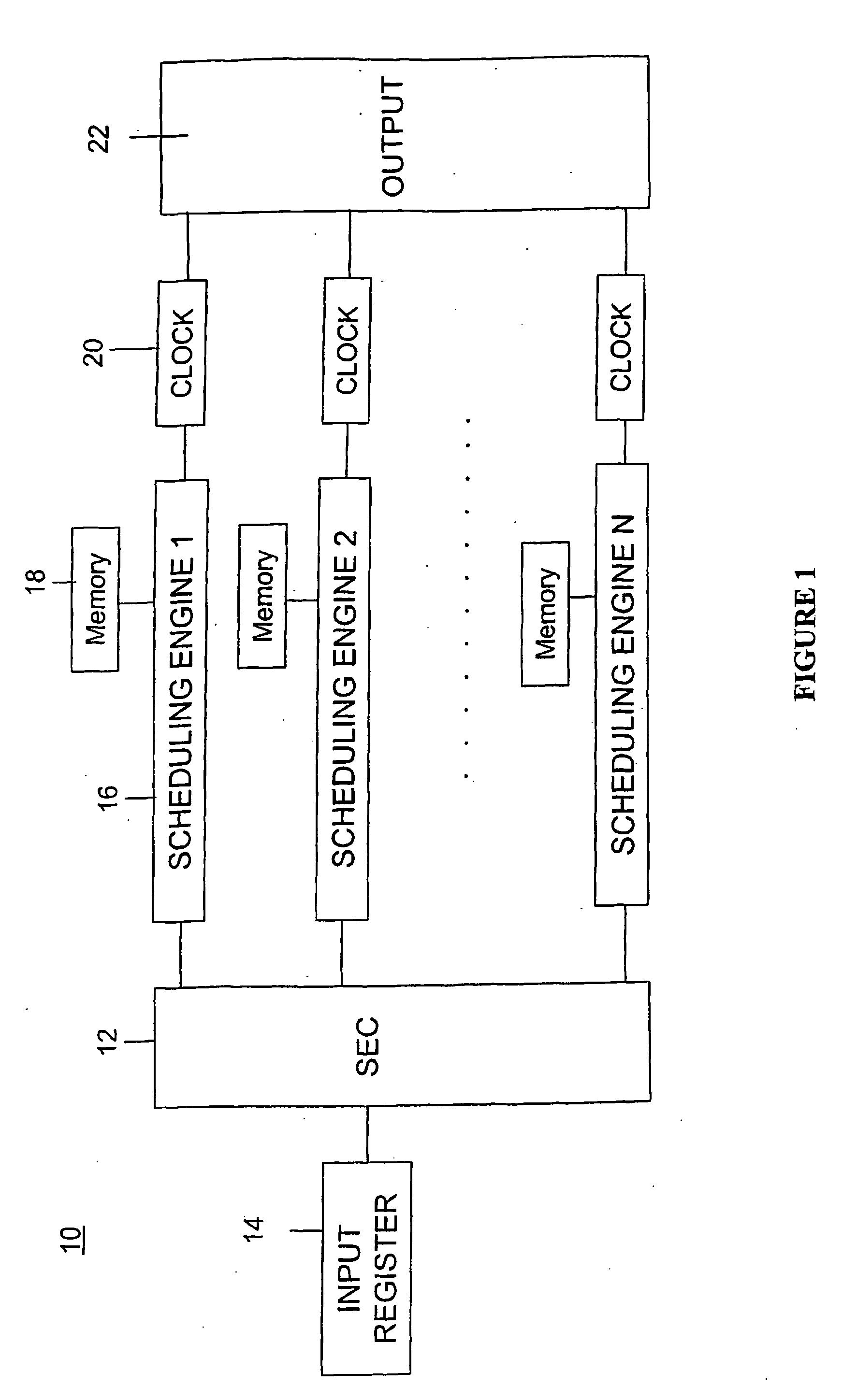
[0030]Referring now to the drawings, wherein like reference numerals designate identical or corresponding parts throughout the several views, FIG. 1 shows one architecture according to the present invention for implementing a scheduler that can handle JIT, JET and Horizon. The scheduler 10 can include an SE controller 12 which takes burst requests from the input first-in first-out (FIFO) register 14. The scheduler 10 then passes these requests to one or more scheduling engines (SEs) 16 to find an appropriate slot where the burst request can be accommodated. The scheduling engines 16 can maintain a database of already scheduled bursts in the plurality of sorted link lists. The database can be stored in memories 18 associated with each scheduling engine 16. After searching the database for available slots, the scheduling engines 16 return the results to the SE controller 12 which selects one of the channels for scheduling the burst (based on a programmable strategy like min-SV, min-EV...


PUM


Abstract

An optical network scheduling device (10) including a plurality of schedulers (16) each corresponding to a respective channel in the optical burst switch network and configured to maintain a transmission schedule for the respective channel; and a controller (12) configured to receive a burst transmission request and to select at least one of the schedulers as a selected scheduler schedule a burst transmission.

Description

BACKGROUND OF THE INVENTION[0001]1. Field of the Invention[0002]The present disclosure relates to optical communication networks and, more particularly, to an Optical Burst-Switching (OBS) network.[0003]2. Discussion of the Background[0004]In addition to the choice of a network's medium and transmission format, network performance is affected by the choice of switching paradigm. For optical networks, Optical Burst Switching (OBS) offers several known advantages. For instance, by eliminating buffering and switching variable size bursts on the fly, OBS enhances network utilization and reduces data latency. Unfortunately, while OBS has achieved some favor with the telecommunications industry, such is not the case for any particular scheduling protocol.SUMMARY OF THE INVENTION[0005]Accordingly, one object of the present invention is to provide an optical network employing an OBS scheduling architecture that accommodates multiple scheduling protocols.[0006]Various of these and other obje...

Claims


Application Information

Patent Timeline
Patent Type & Authority Applications(United States)
IPC IPC(8): H04J14/02H04J3/16
CPCH04J14/0227H04Q2011/0064H04Q11/0066
Inventor MEHROTRA, PRONITASTEVENSON, DANCASSADA, MARKDETTLOFF, WAYNE
Owner RES TRIANGLE INST
Why Eureka
Try Eureka