Systems and Methods for Disinfection

Active Publication Date: 2009-03-26
GEORGIA TECH RES CORP
View PDF5 Cites 34 Cited by
  • Summary
  • Abstract
  • Description
  • Claims
  • Application Information

AI Technical Summary

Benefits of technology

[0015]Methods and systems for meeting the aforementioned needs are provided, More particularly, methods and systems for establishing Taylor-Couette flow in a fluid are provided to address said needs. Aspects of the methods and systems are useful for the

Problems solved by technology

Chlorine treatment, however, presents a number of problems.
Unfortunately, thermal treatment of foodstuff can cause the breakdown of ingredients including proteins and vitamins.
The major limitations to plug flow designs, however, are both non-uniform radiation intensities within the fluid and lo

Method used


Image

  • Systems and Methods for Disinfection
  • Systems and Methods for Disinfection
  • Systems and Methods for Disinfection

Examples


Example

EXAMPLE 1

Taylor Number

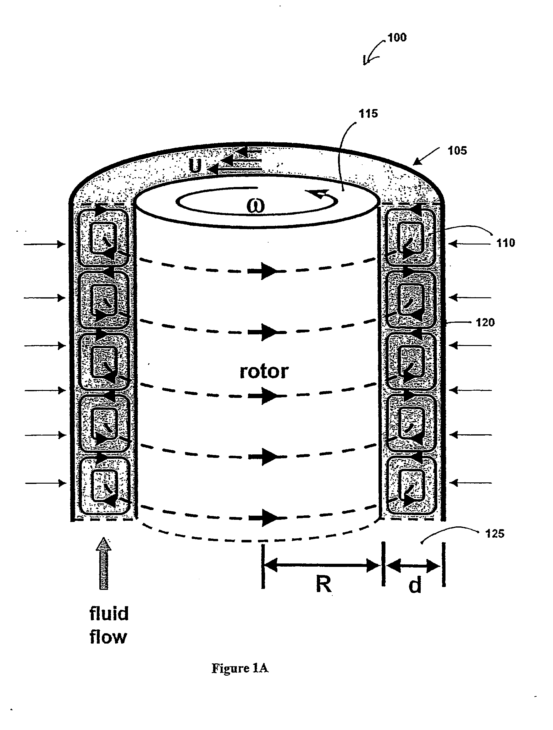
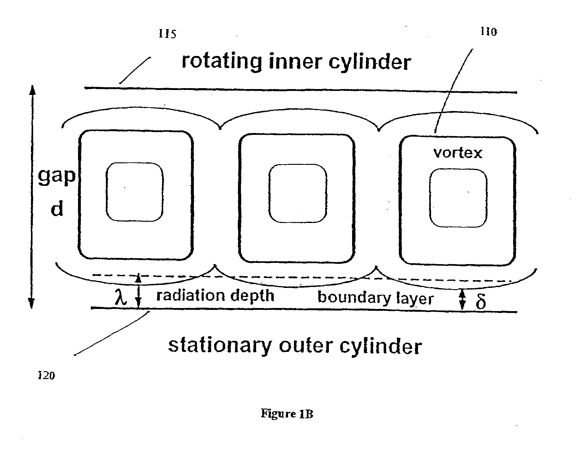
[0077]Values for the inactivation of E. coli in the Taylor column were recorded at increasing rotation rates up to roughly 300 rpm corresponding to a Taylor number of 1000. The data shown in FIG. 6 indicate a minimum of a 4-log reduction in surviving E. coli in units of colony forming units per ml or cfu / ml at a value of Ta=100 or roughly 30 rpm (˜0.5 Hz). Although the value of Ta=100 is somewhat above the critical value of Ta=41 for the onset of laminar Taylor vortices, Ta=100 represented an incremental reduction of roughly 1 or 2-logs in cfu / ml compared to other values of Ta with comparable flow rates as shown in both FIGS. 6 and 7. At roughly Ta=600 the vortices become turbulent and the residence time distribution of the fluid broadens such that the characteristics of the Taylor column approach that of a completely mixed flow-through reactor. For values of 41

Example

EXAMPLE 2

Flow Rate

[0079]Values of E. coli inactivation were recorded at increasing flow rates for three values of the Taylor number Ta=0, 100 and 120. As indicated in FIG. 7 the inactivation levels decreased with higher flow rates for all values of Ta since the radiation dose ∝ 1 / q where q is the volumetric flow rate through the reactor. A value of Ta=100 provides the largest inactivation rates for all recorded flow rates. Significantly, the plot also indicates an increase of over 2-logs for E. coli inactivation compared to simple flow through concentric cylinders (Ta=0) for moderate flow rates of 20 to 40 ml / min.

Example

EXAMPLE 3

Lamp Symmetry

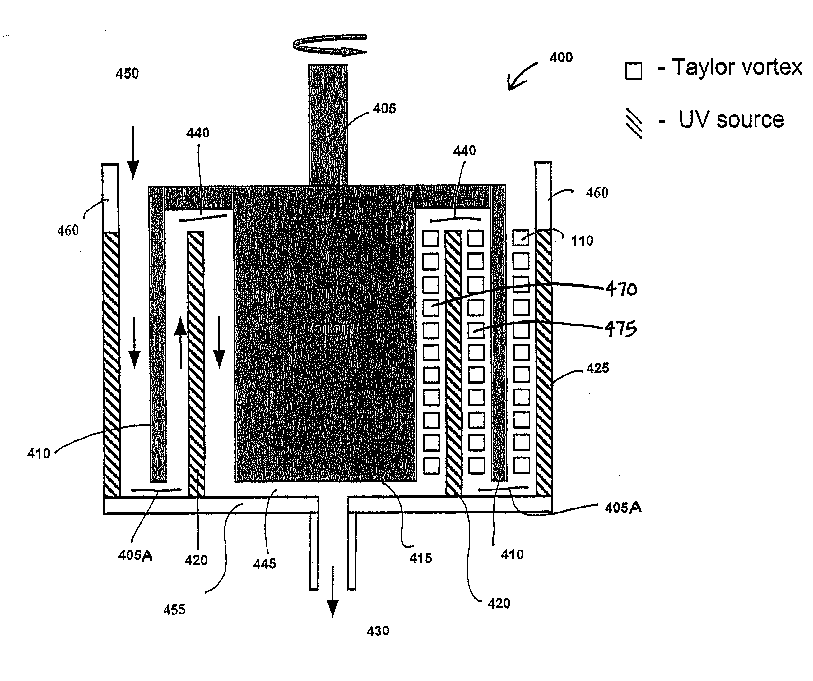
[0080]The effects of lamp location on inactivation were measured and the data are recorded in FIGS. 8 and 9. FIG. 8 with no rotation or Ta=0 demonstrates that channeling of the pathogens occurs between concentric cylinders when the lamps are grouped on the side of the reactor opposite the fluid inlet.

[0081]For the symmetrical case of equidistant lamp location and at Ta=100, FIG. 9 illustrates that an improvement of over a 1-log reduction in surviving organisms was again observed compared to the grouped geometry for moderate flow rates between 2060 ml / min at lower photon dosages. One concludes that there is a significant loss of photons from both reflection and transmission through multiple lamps in close proximity,


PUM


Abstract

Methods and systems for establishing Taylor-Couette flow in a fluid are provided. Aspects of the disclosed methods and systems incorporate laminar Taylor-Couette flow in combination with a source of radiation to provide more uniform radiation exposure to the fluid and its components. Common problems of non-uniform radiation levels and concentration boundary layer effects in UV reactors are largely eliminated using the methods and devices provided herein. In an exemplary embodiment, the reactor of the present disclosure has a hollow outer cylinder or stator and a rotor positioned therein and smooth walls for both the outer wall of its rotor and the inner wall of the outer cylinder or stator in which the rotor is positioned, the space between which forming the annular fluid gap.

Description

CROSS REFERENCE TO RELATED APPLICATIONS[0001]This application is a continuation-in-part of co-pending U.S. application Ser. No. 11 / 359,005, filed Feb. 21, 2006, which is a continuation-in-part of U.S. application Ser. No. 10 / 692,983, filed Oct. 24, 2003, now U.S. Pat. No. 7,001,571, that claims the benefit of U.S. Provisional Patent Application No. 60 / 420,985 filed on Oct. 24, 2002, and to U.S. Provisional Patent Application No. 60 / 461,326 filed on Apr. 8, 2003, all of which are incorporated herein by reference in their entirety. This application also claims priority to and the benefit of U.S. Provisional Patent Application No. 60 / 974,891, filed Sep. 25, 2007, which is also incorporated herein by reference in its entirety.BACKGROUND[0002]1. Technical Field[0003]The present disclosure is related generally to methods and systems for moving fluids, more particularly, methods and systems for generating fluid flow that increases fluid exposure to an energy source for sterilization or dis...

Claims


Application Information

Patent Timeline
IPC IPC(8): A23L3/28C02F1/30A23L3/26
CPCA23L3/28C02F1/006C02F1/325C02F2303/04C02F2301/022C02F2301/024C02F2201/328Y02W10/37
Inventor FORNEY, LARRY
Owner GEORGIA TECH RES CORP
Why Eureka
Try Eureka