Microfluidic radiation damage biological dosimetry detection device and its detection and analysis method based on luminescent bacteria
A technology of radiation damage and luminescent bacteria, applied in the field of nuclear radiation and space radiation damage biological dose assessment, ultraviolet and ionizing radiation, it can solve the problems of long sample preparation and detection time, lack of blank contrast, poor detection accuracy, etc., to ensure accurate The effect of reducing the cost of detection and use
- Summary
- Abstract
- Description
- Claims
- Application Information
AI Technical Summary
Problems solved by technology
Method used
Image
Examples
specific Embodiment approach 1
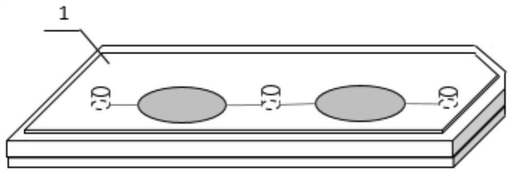
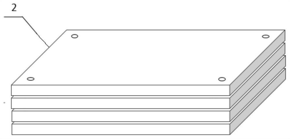
[0071] Specific implementation mode one: combine Figure 1~5 This embodiment is specifically described. The microfluidic radiation damage biological dose analysis and detection device based on luminescent bacteria in this embodiment consists of a microfluidic chip 1, an irradiation fixture 2, a condenser lens 3, an optical fiber 4, a photomultiplier tube 5, Composed of pulse counter 6 and device main body 7;
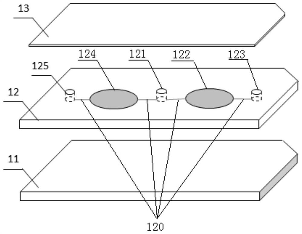
[0072] The microfluidic chip 1 is composed of a chip bottom layer 11, a microchannel layer 12 and a self-adhesive film layer 13, and the chip bottom layer 11, the microchannel layer 12 and the self-adhesive film layer 13 are stacked sequentially from bottom to top; A sample inlet 121, a microchannel 120, a control zone microchamber 122, an irradiation zone microchamber 124, a control zone microchamber outlet 123 and an irradiation zone microchamber outlet 125 are provided, and the sample inlet 121 passes through the microchannel 120 respectively. It is connected with th...
specific Embodiment approach 2
[0076] Embodiment 2: The difference between this embodiment and Embodiment 1 is that the microchamber 122 in the control area and the microchamber 124 in the irradiation area are both circular chambers or consist of a plurality of small chambers or channels. Composed in series. Others are the same as in the first embodiment.
specific Embodiment approach 3
[0077] Specific implementation mode three: combination Figure 6 This embodiment is described in detail. The difference between this embodiment and one of the specific embodiments 1 or 2 is: when the microchamber 122 in the control area and the microchamber 124 in the irradiation area are composed of a plurality of small chambers connected in series , the plurality of small chambers are horizontally arranged side by side and connected in series end to end, the radius of curvature of the microchannel 120 connected between the small chambers is 1mm, and the gap between the small chambers in the longitudinal direction is 1mm. The chambers are all arrow-shaped quadrilaterals, the width of the small chamber is 2mm at the widest, the length of the short side is 1.8mm, the length of the small chamber is 13mm, and the depth is 100 μm; when the microchamber 122 in the control area and the irradiation area When the microchambers 124 are all circular chambers, the diameter of the circula...
PUM
| Property | Measurement | Unit |
|---|---|---|
| length | aaaaa | aaaaa |
| depth | aaaaa | aaaaa |
| diameter | aaaaa | aaaaa |
Abstract
Description
Claims
Application Information
 - R&D
- Intellectual Property
- Life Sciences
- Materials
- Tech Scout
- Unparalleled Data Quality
- Higher Quality Content
- 60% Fewer Hallucinations
Browse by: Latest US Patents, China's latest patents, Technical Efficacy Thesaurus, Application Domain, Technology Topic, Popular Technical Reports.
© 2025 PatSnap. All rights reserved.Legal|Privacy policy|Modern Slavery Act Transparency Statement|Sitemap|About US| Contact US: help@patsnap.com


