Pressure wire assembly

a pressure wire and wire assembly technology, applied in the field of assembly, can solve the problems of not being able to connect directly to many patient monitors already in use, the use of newer miniaturized sensors, and the inability to operate over the entire range of excitation signal magnitude and frequency, etc., and achieve the effect of low over all cost and convenient us

Active Publication Date: 2009-03-26
ST JUDE MEDICAL COORDINATION CENT
View PDF13 Cites 101 Cited by
  • Summary
  • Abstract
  • Description
  • Claims
  • Application Information

AI Technical Summary

Problems solved by technology

For instance, the miniaturized sensors often cannot operate over the entire range of excitation signal magnitudes and frequencies found among the various types of patient monitors.
Thus, they cannot be connected directly to many of the patient monitors already in use.
Such an arrangement necessitates additional circuitry on the interface and, because existing monitors have been designed to provide only limited amounts of power, the additional circuitry may require an independent source of electrical power.
As a consequence, use of the newer miniaturized sensors often adds cost and complexity to the overall system.
As discussed, this does not conform with the electrical format required by the many monitors that are commercially available and already in widespread use.
As such, the newer sensors can only be used with specific signal conditioning and displaying units, thereby requiring additional equipment to be purchased.
This is especially undesirable given the cost sensitivities so prevalent in today's health care environment.
An obvious drawback of the device of U.S. Pat. No. 5,568,815 is that, in order to connect the sensor to the monitor, a separate additional unit in the form of the interface circuit is required.
As such, the accuracy of such systems has suffered due to variations in hydrostatic pressure and other inconsistencies associated with the fluid column.

Method used


Image

  • Pressure wire assembly
  • Pressure wire assembly
  • Pressure wire assembly

Examples


first embodiment

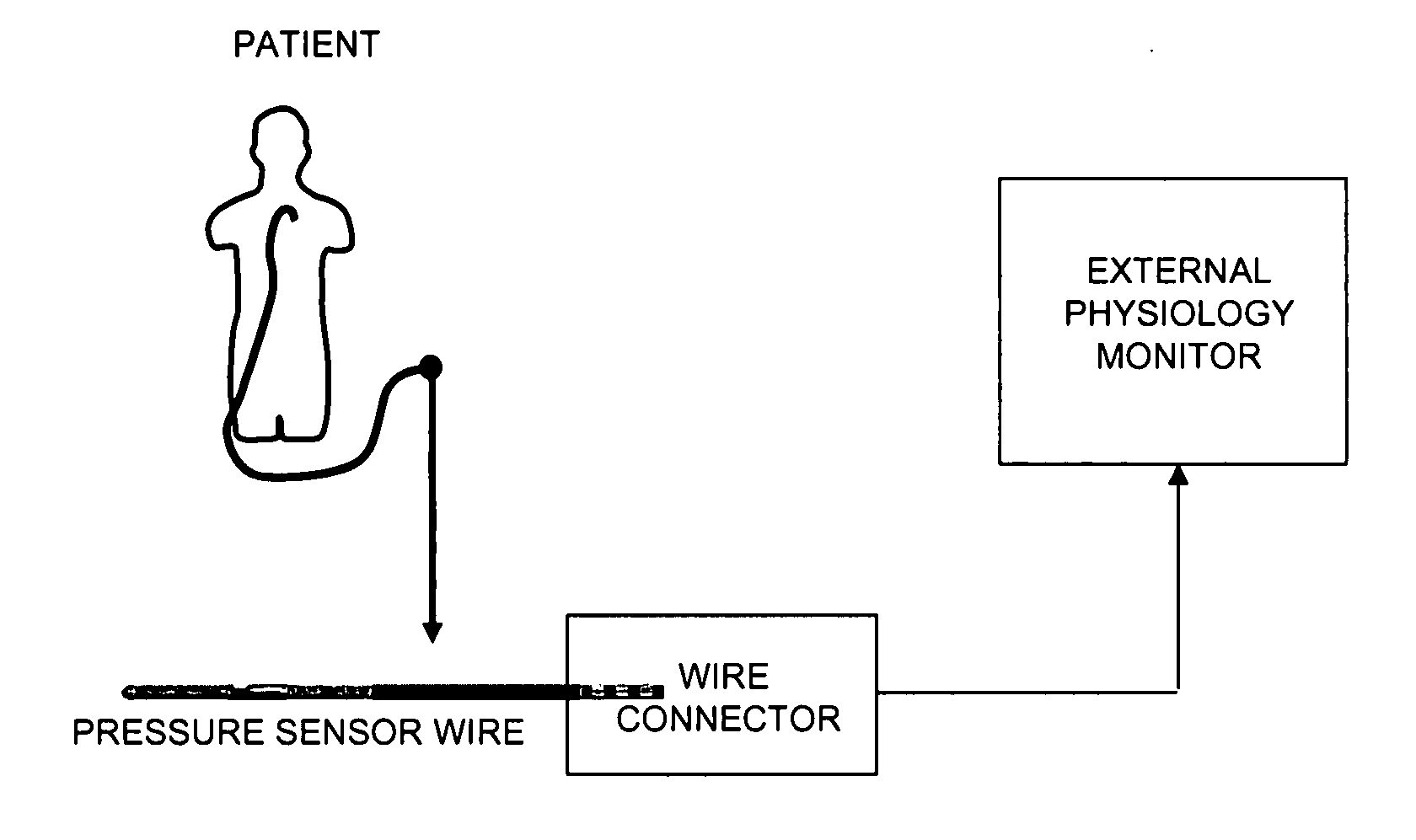
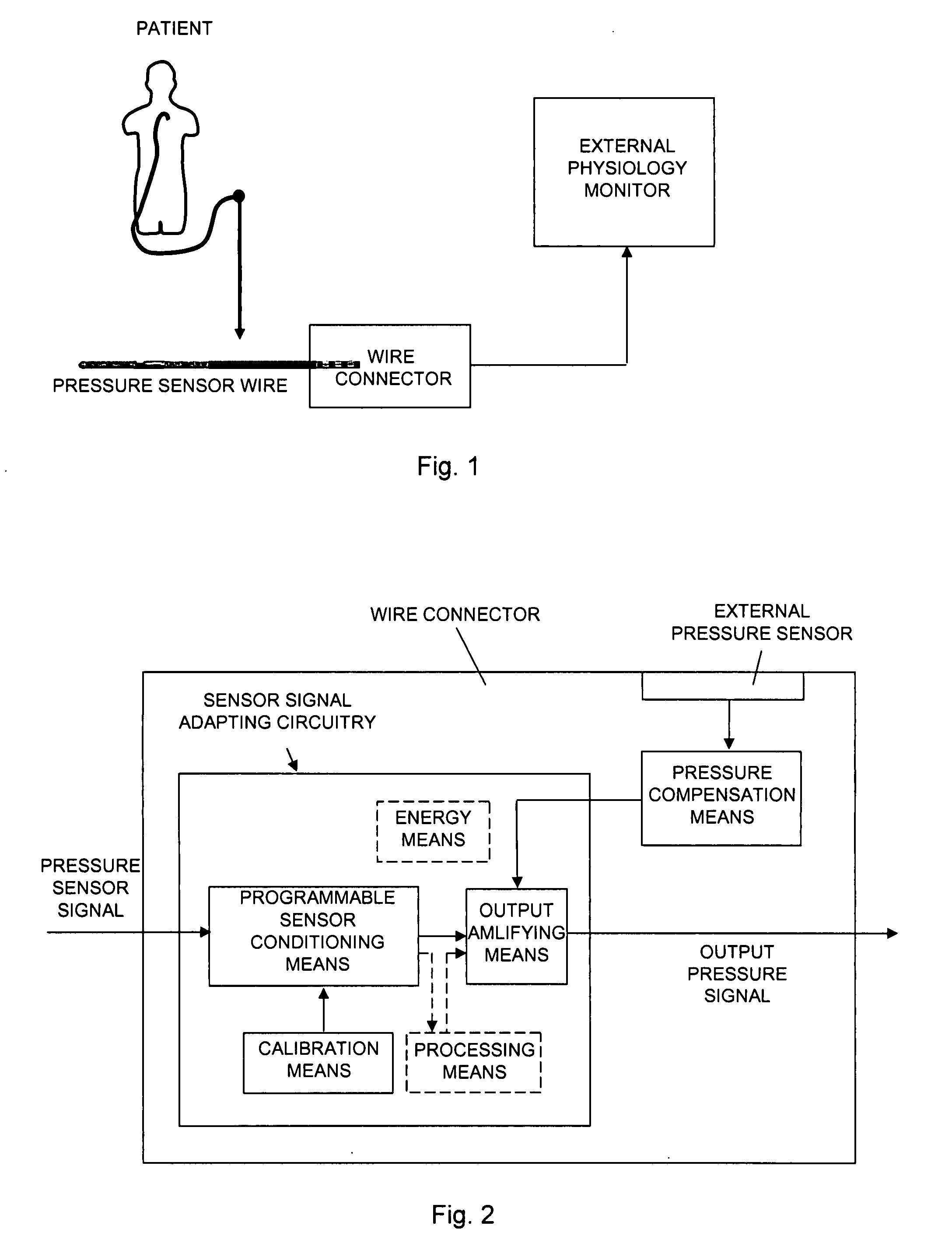
[0024]FIG. 1 schematically illustrates a pressure sensor wire assembly for measuring pressure in a body of a patient, and FIG. 2 shows a block diagram schematically illustrating a wire connector according to the present invention.

[0025]With references to FIG. 2 the present invention relates to a pressure sensor wire assembly for measuring pressure inside a body of a patient. The assembly comprises a pressure sensor element, not shown in the figure, for measuring pressure and to generate a pressure sensor signal in response of the measured pressure, a pressure sensor wire (FIG. 1) having the pressure sensor element at its distal portion, and adapted to be inserted into the body of a patient in order to position the sensor element within the body. The assembly further comprises a sensor signal adapting circuitry, being an integrated part of the assembly, wherein the pressure sensor signal is applied to the adapting circuitry that is adapted to automatically generate an output pressure...

third embodiment

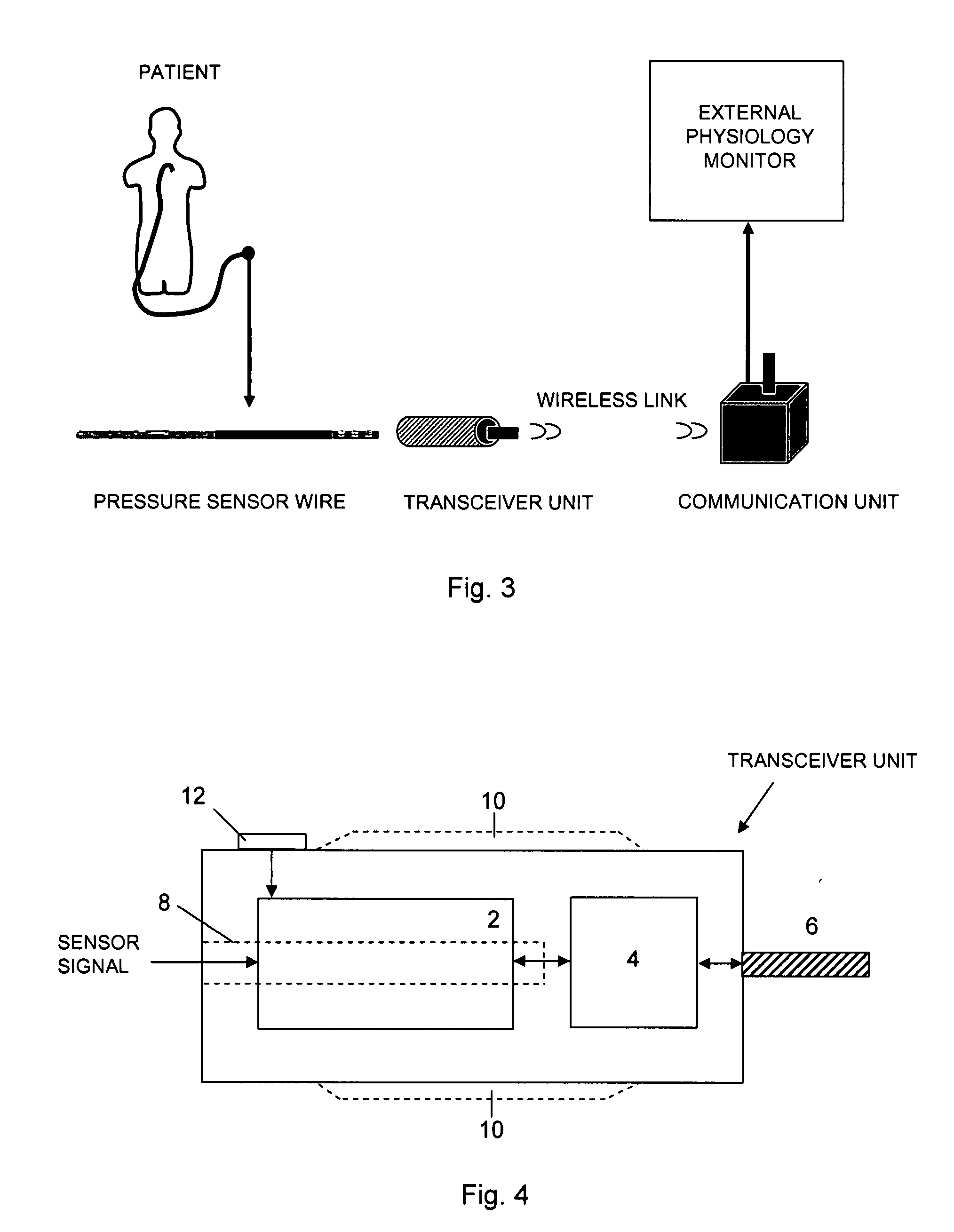
[0040]FIG. 3 schematically illustrates the present invention according to a second and a third embodiment where the assembly comprises a transceiver unit and a communication unit. The pressure sensor wire is adapted to be connected, at its proximal end, to the transceiver unit that is adapted to wirelessly communicate via a communication signal with the communication unit, and the communication unit is in turn connected to the external physiology monitor, in order to transfer the output pressure signal to the external physiology monitor.

[0041]FIG. 4 schematically shows the transceiver unit of the second or third embodiment of the present invention.

[0042]The second and third embodiments, where the communication signal is a radio frequency signal, will now be described in detail. The wireless communication is performed by using an established communication protocol, e.g. Bluetooth. Although the transceiver unit and the communication unit are described in connection with the use of a r...

second embodiment

[0057]In the second embodiment the external pressure sensor is either energized by the energy means within the communication unit, or energized via the external monitor and / or via external mains suppy. The energy means may be e.g. a battery or capacitor.

[0058]Similarly, the third embodiment is illustrated by FIGS. 7 and 8, where the processing and conditioning means should be omitted in FIG. 8. An alternative third embodiment is illustrated by FIGS. 7 and 8 where instead the programmable sensor conditioning means should be omitted in FIG. 7.

[0059]In the third embodiment the external pressure sensor is energized by the energy means within the transceiver unit, preferably the same energy means the energizes the circuitry of the connected pressure sensor wire. The energy means may be e.g. a battery or capacitor.


PUM


Abstract

Pressure sensor wire assembly for measuring pressure inside a body of a patient, the assembly comprises a pressure sensor element for measuring pressure and to generate a pressure sensor signal in response of said pressure, and a pressure sensor wire having said pressure sensor element at its distal portion, and adapted to be inserted into the body in order to position the sensor element within the body. In addition is arranged a sensor signal adapting circuitry, being an integrated part of said assembly, wherein the pressure sensor signal is applied to the adapting circuitry that is adapted to automatically generate an output pressure signal, related to the sensor signal, in a standardized format such that the measured pressure is retrievable by an external physiology monitor. The assembly further comprises an external pressure sensor arranged at the assembly to measure the pressure outside the patient's body and to generate external pressure values in dependence thereto, the external pressure values are applied to a pressure compensation means, in the assembly, adapted to generate a compensation value reflecting the external pressure variation during a measurement procedure, wherein the output pressure signal is compensated by said compensation value prior to the output pressure signal being applied to the external physiology monitor.

Description

FIELD OF THE INVENTION[0001]The present invention relates to an assembly according to the preamble of the independent claim.BACKGROUND OF THE INVENTION[0002]A sensor wire assembly is known from EP-1,774,905 assigned to the assignee of the present application for measuring a physiological variable, in particular pressure, inside a patient's body. The pressure sensor used in the EP-document is a miniaturized semiconductor sensor and one purpose of the assembly of EP-1,774,905 is to handle the electrical configurations of these miniaturized semiconductor sensors that are not always compatible with the transducer amplifiers in existing patient monitors. For instance, the miniaturized sensors often cannot operate over the entire range of excitation signal magnitudes and frequencies found among the various types of patient monitors. Thus, they cannot be connected directly to many of the patient monitors already in use. To be used with such existing monitors, a specialized interface must b...

Claims


Application Information

Patent Timeline
Patent Type & Authority Applications(United States)
IPC IPC(8): A61B5/0215
CPCA61B5/6851A61B5/0215
Inventor SMITH, LEIF
Owner ST JUDE MEDICAL COORDINATION CENT
Why Eureka
Try Eureka