A floating pressing roller and a winding machine comprising the floating pressing roller

A technology of pressing roller and frame, which is applied in the field of textile and chemical fiber machinery, can solve the problems of poor parallelism of two bobbin chuck axes, finishing of winding machine, difficulty of assembly, debugging and maintenance, etc., and achieve good contact effect

Active Publication Date: 2015-08-05
BEIJING CHONGLEE MACHINERY ENG
View PDF4 Cites 0 Cited by
  • Summary
  • Abstract
  • Description
  • Claims
  • Application Information

AI Technical Summary

Problems solved by technology

[0006] The technical problem to be solved by the present invention is to provide a floating press roller, which solves the problem that in the prior art, the installation method of the press roller requires that the parallelism deviation of the two bobbin chuck axes of the winding machine is small, but due to the The increase in the length of the chuck shaft will inevitably lead to the poor parallelism of the chuck shafts of the two bobbins, which will cause great difficulties in the finishing, assembly, debugging and maintenance of the winding machine.

Method used


Image

  • A floating pressing roller and a winding machine comprising the floating pressing roller
  • A floating pressing roller and a winding machine comprising the floating pressing roller
  • A floating pressing roller and a winding machine comprising the floating pressing roller

Examples


Embodiment Construction

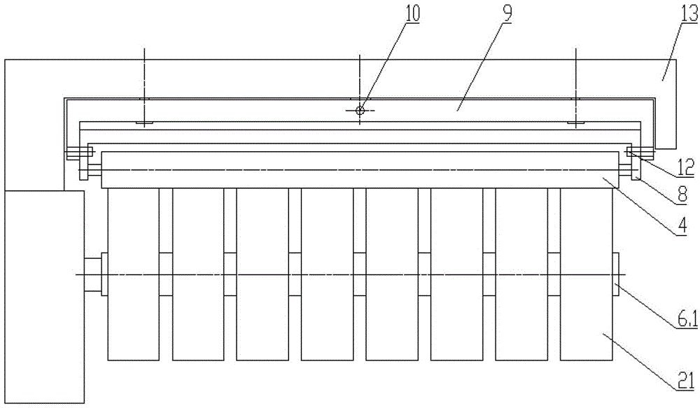
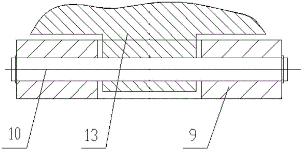
[0029] see figure 1 and figure 2 As shown, the floating pressing roller provided by the embodiment of the present invention includes a second bracket 8 and a first bracket 9, and the left and right ends of the pressing roller 4 are rotatably mounted on the two arms of the second bracket 8 through bearings. Inside, the two arms of the second bracket 8 are formed by bending the left and right ends of the second bracket 8 . The second bracket 8 is installed on the two arms of the first bracket 9 through pin shafts 12 , wherein the two arms of the first bracket 9 are formed by bending the left and right ends of the first bracket 9 . Such as image 3 As shown, the first bracket 9 is connected to the frame 13 through a shaft.

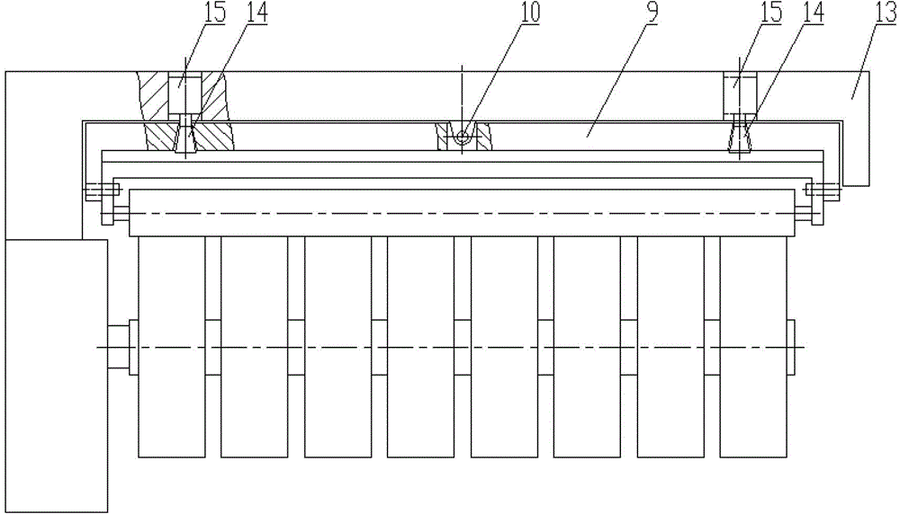
[0030] see figure 2 , at the left and right ends of the first bracket 9, two locking pins 14 are installed. The locking end of the locking pin 14 is movably connected with the first bracket 9 through the hole provided on the first bracket 9, and the ot...


PUM


Abstract

The invention discloses a floating pressure wire roller and a coiler containing the floating pressure wire roller. The floating pressure wire roller comprises a first support which is connected with a rack through a shaft; the connecting point of the first support and the rack is located between the left end and the right end of the first support; the first support uses the connecting point as a supporting point, and the left end and the right end of the first support can swing vertically; and the two ends of the floating pressure wire roller are movably connected with the first support. The floating pressure wire roller is connected with a second support through a bearing, the second support is connected with the first support through a pin shaft, and the first support is connected with the rack through a pivot shaft. The first support enables the left end and the right end of the pressure wire roller to swing vertically, the second support enables the pressure wire roller to swing back and forth, and therefore the pressure wire roller is automatically parallel to bobbin clamping head shafts located at the work position and pressed on the periphery of the bobbin clamping head shafts in a floating mode even though parallelism deviation of the two bobbin clamping head shafts is large, and good contact between the pressure wire roller and the bobbin clamping head shafts is kept.

Description

technical field [0001] The invention relates to the field of textile and chemical fiber machinery, in particular to a floating pressing roller and a winding machine comprising the floating pressing roller. Background technique [0002] The chemical fiber filament winding machine is used for continuous winding of filaments. A rotatable turntable is installed in the frame of the automatic winding machine, and two protruding rotatable bobbin chucks are mounted on the cantilever on the turntable. Shaft, each bobbin chuck shaft is equipped with a plurality of paper bobbin tubes, a pressing roller is installed above the working bobbin chuck shaft, and a traversing device is arranged above the pressing roller. [0003] During a winding cycle, the wire pressing roller contacts with the circumference of the silk cake being formed on the working bobbin chuck shaft with a certain pressure, and the rotation of the turntable makes the pressure roller and the working bobbin chuck shaft co...

Claims


Application Information

Patent Timeline
Patent Type & Authority Patents(China)
IPC IPC(8): B65H67/048
Inventor 宁波李素敏李学庆李玉鑫李喆
Owner BEIJING CHONGLEE MACHINERY ENG
Why Eureka
Try Eureka