Storage sub-system and method for controlling the same

a subsystem and storage technology, applied in the field of storage subsystems, can solve the problems that the data reduction control technique called “data de-duplication” cannot be combined in the situation described above, and the data guarantee code check error cannot be used in the data guarantee code. the effect of reducing the amount of data

Active Publication Date: 2009-03-26
HITACHI LTD
View PDF6 Cites 43 Cited by
  • Summary
  • Abstract
  • Description
  • Claims
  • Application Information

AI Technical Summary

Benefits of technology

[0018]It is an object of the present invention to provide a storage sub-system that can utilize a data check technique using a data guarantee code...

Problems solved by technology

However, if there is no such a mechanical failure and the disk array controller can read data from disks, but if there is a failure like in the case where the data is not written at a correct address in the disk due to trouble or the data being garbled, RAID cannot deal with such a failure.
Because of de-duplication, the disk array controller refers to data A in response to the read request for data B. Therefore, the data guarantee code for the read data is based on the logical address of data A. However, since the disk array controller performs checking with the expectation to find the data guarantee code corresponding to data B, it determin...

Method used


Image

  • Storage sub-system and method for controlling the same
  • Storage sub-system and method for controlling the same
  • Storage sub-system and method for controlling the same

Examples


first embodiment

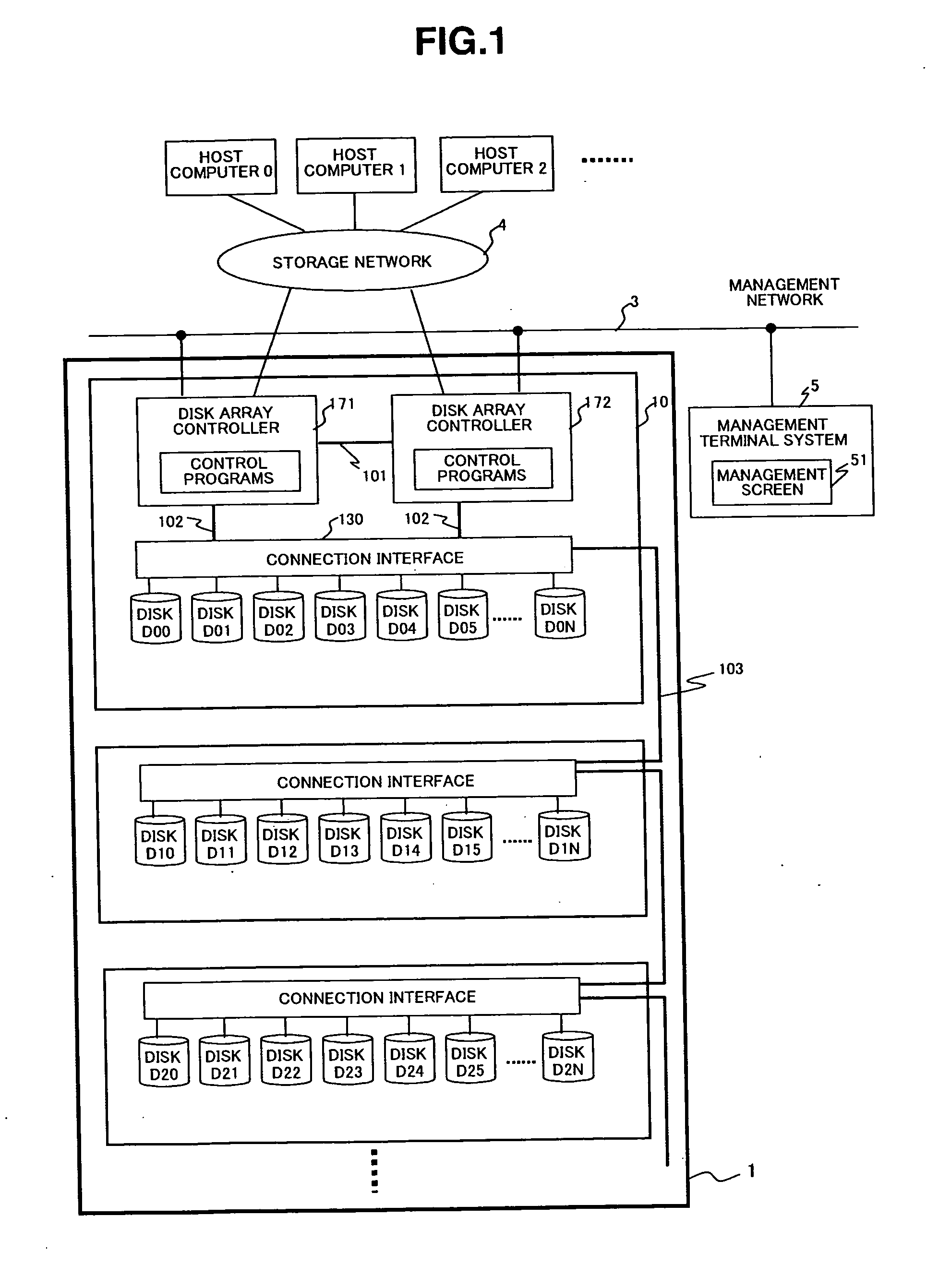
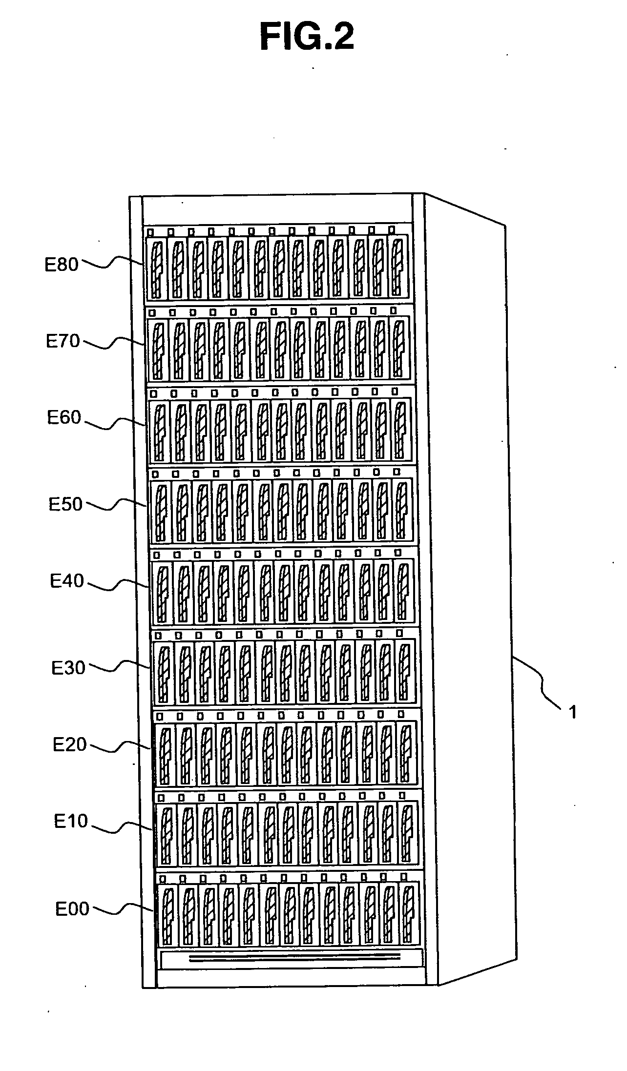
[0052]FIG. 2 is an external view showing the configuration of a disk array apparatus according to the The disk array apparatus 1 contains the disk array controller 171 and other disk array controllers, the disk D00 and other disks, fans, and a power source 8; and the disk array apparatus 1 is configured by connecting a plurality of housings such as disk storage housings E00, E10, and so on up to E80, depending on the number of disks.

[0053]FIG. 3 is a block diagram showing the internal configuration of the disk array controller 171 according to the first embodiment. Incidentally, the disk array controller 172 has the same internal configuration.

[0054]The disk array controller 171 includes a CPU 1901, memory 1902, a data operation and transfer controller 1904, a data buffer 1907, a host connection interface controller 1905, a backend connection interface controller 1906, and a LAN interface controller 1908. They are connected to each other via data transfer paths suitable for that pu...

second embodiment

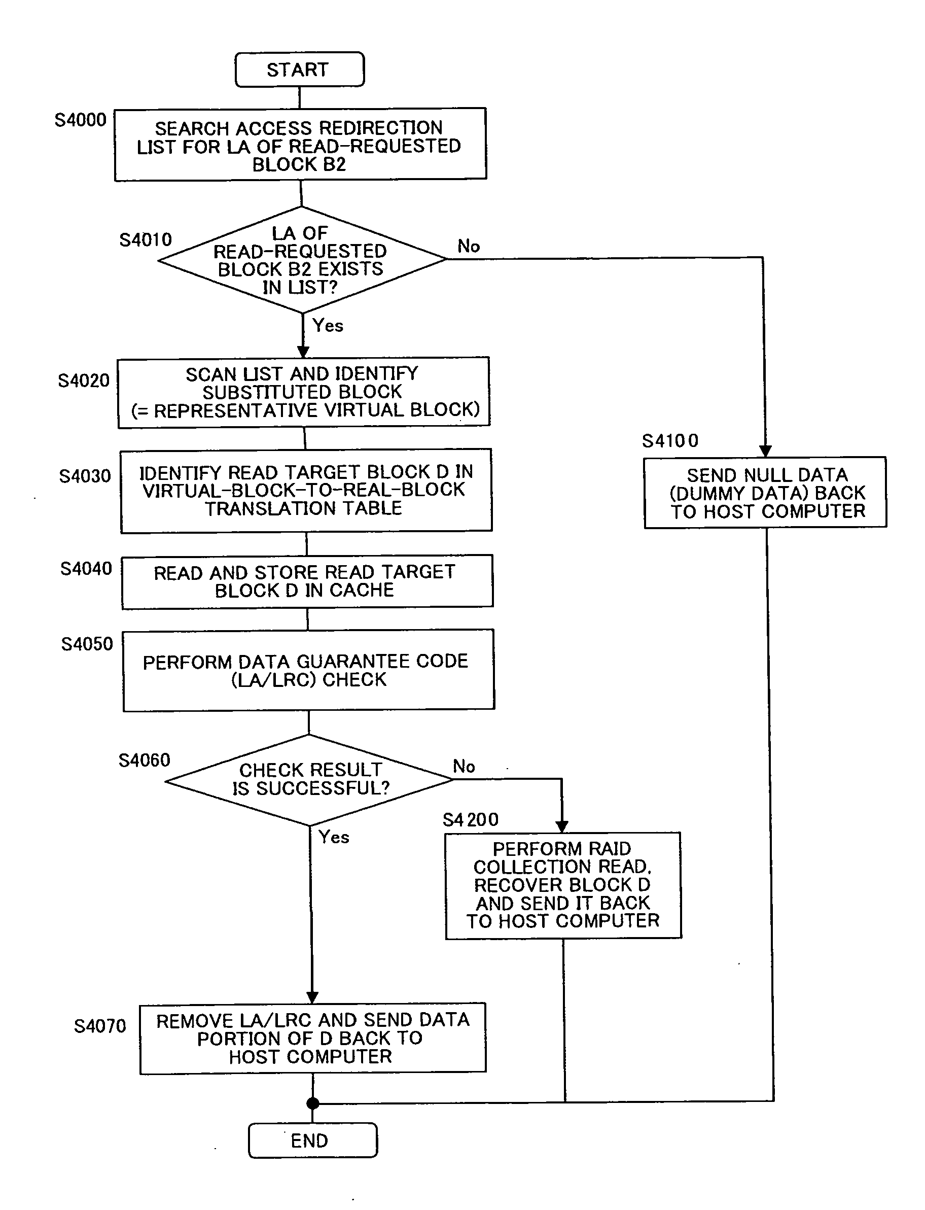
[0112]FIG. 16 is an explanatory diagram of the configuration of the access redirection list T10 according to the The access redirection list T10 retains, in a list configuration, the LAs of blocks on the virtual volume that refer to the same data content in de-duplication. This table shows that, for example, blocks B1, B2, and B7 are blocks in the virtual volume that refer to the same data content, and accesses to these blocks are represented by block B1 that is an element of the list configuration.

[0113]FIG. 17 is an explanatory diagram of the configuration of the virtual-block-to-real-block translation table T11 according to the second embodiment. The virtual-block-to-real-block translation table T11 manages a correspondence relationship between representative access blocks on the virtual volume and real blocks on the pool volume, using LAs.

[0114]FIGS. 18-1 and 18-2 are flowcharts illustrating duplicate data elimination processing executed by the de-duplication control program 19...


PUM


Abstract

The present invention provides means for effectively reducing the amount of data by means of de-duplication in a disk array apparatus having a data guarantee code.
A control means for the disk array apparatus that adds a data guarantee code to each logical data block and checks the data guarantee code when reading data has a de-duplication performing function and control means for: generating LA substitution information for a function checking the data guarantee code or read data location address substitution information when performing the de-duplication and storing data; performing the de-duplication using the above-mentioned information when reading data; and thereby avoiding false diagnosis of the data guarantee code check.

Description

CROSS-REFERENCES TO RELATED APPLICATIONS [0001]This application relates to and claims priority from Japanese Patent Application No. 2007-250139, filed on Sep. 26, 2007, the entire disclosure of which is incorporated herein by reference.BACKGROUND [0002]1. Field of the Invention[0003]The invention relates to a storage sub-system having a data de-duplication function and a method for controlling the storage sub-system.[0004]2. Description of Related Art[0005]A disk array apparatus storage sub-system is configured so that a plurality of magnetic disks or semiconductor disks such as SSD (Solid State Disks) using nonvolatile memory or similar are arranged in arrays and placed under control of a disk array controller. The disk array apparatus processes at high speed a read request (data read request) and a write request (data write request) from host computers by operating a plurality of disks in parallel.[0006]Many disk array apparatuses employ a data redundancy technique called “RAID (R...

Claims


Application Information

Patent Timeline
IPC IPC(8): H03M13/09G06F11/10
CPCG06F3/0608G06F3/0619G06F3/0641G06F3/0643G06F2211/1057G06F11/1076G06F11/2089G06F2211/1004G06F3/067
Inventor ARAI, MASAHIROSHIMADA, KENTARONAKAMURA, SHUJI
Owner HITACHI LTD
Why Eureka
Try Eureka