Combustor assembly including one or more resonator assemblies and process for forming same

a technology of resonator assembly and combustor, which is applied in the direction of fluid couplings, lighting and heating apparatus, couplings, etc., can solve the problems of reducing the life of combustion assembly components or restricting engine operation, altering the damping performance of the combustion assembly, and oscillating the acoustic pressure of the combustion assembly

Active Publication Date: 2009-04-02
SIEMENS ENERGY INC
View PDF18 Cites 37 Cited by
  • Summary
  • Abstract
  • Description
  • Claims
  • Application Information

AI Technical Summary

Benefits of technology

[0016]Applying masking material comprises applying the masking material so as to encompass each of the slots in the gen

Problems solved by technology

The coupling of heat release oscillations with the acoustics of the combustor assembly is known to cause combustor acoustic pressure oscillations.
These pressure oscillations in the combustor assembly can cause high cycle fatigue, leading to reduced life of combustion assembly components or restricted engine operation.
However, the thermal barrier coating can lengthen a neck of each Helmholtz resona

Method used


Image

  • Combustor assembly including one or more resonator assemblies and process for forming same
  • Combustor assembly including one or more resonator assemblies and process for forming same
  • Combustor assembly including one or more resonator assemblies and process for forming same

Examples


first embodiment

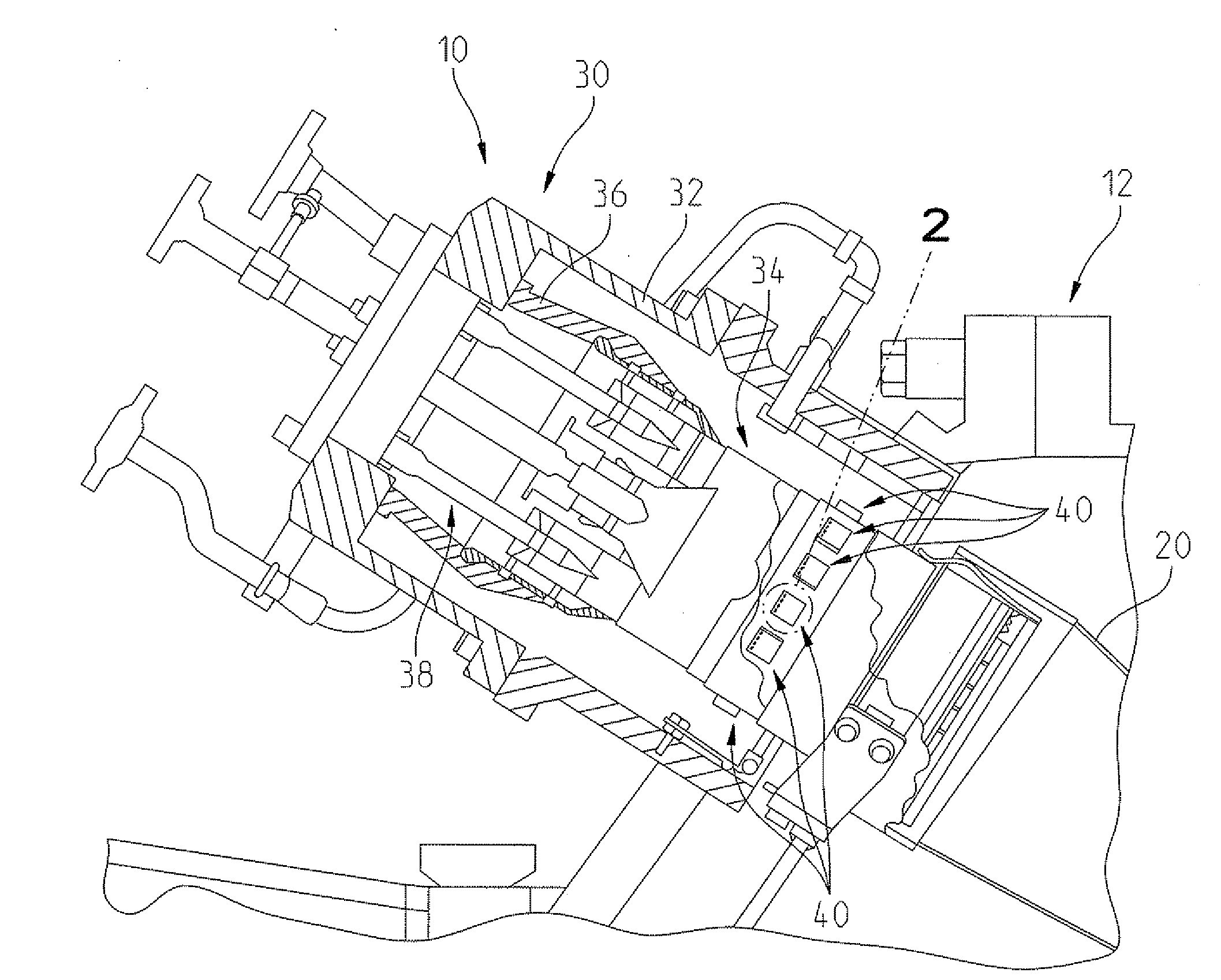
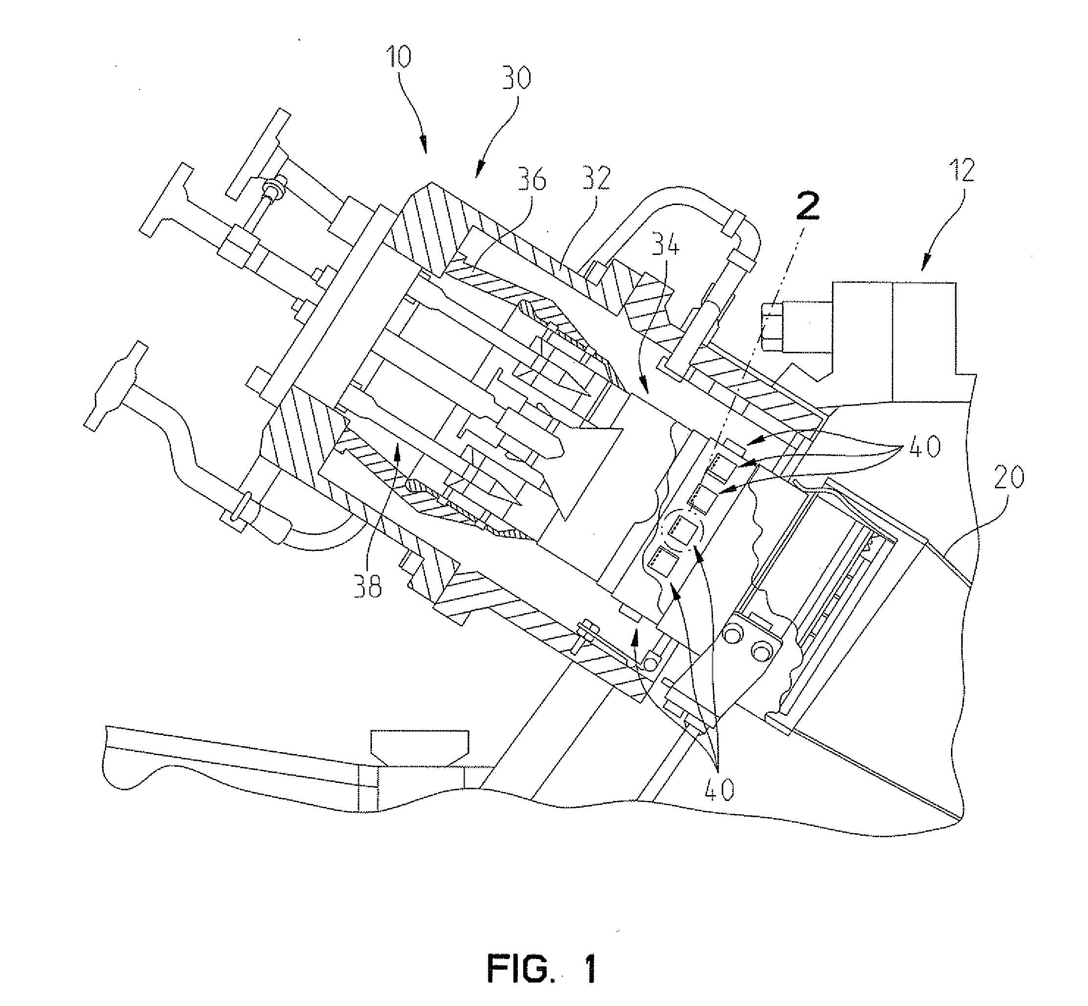
[0030]A plurality of resonator assemblies 40 constructed in accordance with the present invention are spaced apart circumferentially about the liner 34, see FIG. 1. For example, there may be between about 4 and about 30 resonator assemblies 40 associated with the liner 34. The resonator assemblies 40 comprise Helmholtz resonators and function to control or damp combustion acoustic pressure oscillations generated during combustion of the air and fuel mixture. See U.S. Pat. No. 6,530,221, the disclosure of which is incorporated by reference herein, for a further discussion of Helmholtz resonators. Each resonator assembly 40 is constructed in the same manner. Hence, only the resonator assembly 40 illustrated in FIG. 2 will be described in detail herein.

[0031]The resonator assembly 40 comprises a resonator outer plate 42 having a plurality of openings 42A, which, in the illustrated embodiment, are elliptical and aligned along an axis A1, see FIG. 2. Alternatively, the openings 42A may b...

second embodiment

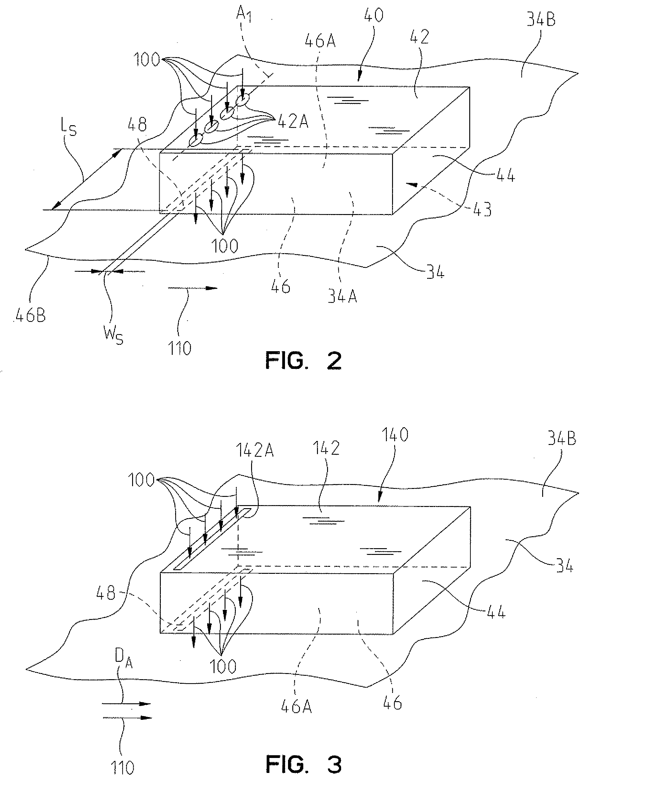
[0032]A resonator assembly 140 constructed in accordance with the present invention is illustrated in FIG. 3, wherein like reference numerals indicate like elements. The resonator assembly 140 is substantially similar to the resonator assembly 40 illustrated in FIG. 2, except that a slot 142A is provided in the outer plate 140 instead of a plurality of openings 42A. While only a single slot 142A is illustrated in FIG. 3, more than one slot 142A may be provided. In the illustrated embodiment, the slot 48 extends generally circumferentially about the liner 34. The slot 142A is generally parallel to the slot 48 and also generally aligned to the slot 48 in an axial direction DA.

third embodiment

[0033]A resonator assembly 240 constructed in accordance with the present invention is illustrated in FIG. 4, wherein like reference numerals indicate like elements. The resonator assembly 240 is substantially similar to the resonator assembly 140 illustrated in FIG. 3, except that a slot 242A in a resonator outer plate 242 is spaced in the axial direction DA from the slot 48 provided in the resonator inner plate 46. In the illustrated embodiment, the slot 48 extends generally circumferentially about the liner 34. The slot 242A is generally parallel to the slot 48. It is further contemplated that the slot 242A may be replaced by a plurality of openings 1242A, which may be aligned along a common axis, see FIG. 4A.


PUM


Abstract

A combustor assembly is provided comprising a combustor casing; a liner coupled to the combustor casing; a burner assembly coupled to the combustor casing; and at least one resonator assembly. The resonator assembly comprises a resonator outer plate having at least one opening, a resonator side wall coupled to the resonator outer plate, and a resonator inner plate defined by a portion of the liner. The resonator inner plate is coupled to the resonator side wall and has at least one slot formed therein having an aspect ratio of at least 4:1.

Description

FIELD OF THE INVENTION[0001]The present invention relates to a combustor assembly including one or more resonator assemblies and a process for forming same.BACKGROUND OF THE INVENTION[0002]Gas turbine engines including a can-annular combustion system comprise a compressor and a turbine. The can-annular combustion system comprises a plurality of combustor assemblies and a like number of transition ducts. In one design, these combustor assemblies comprise a combustor casing, a burner assembly, and a combustor liner. Each transition duct connects a corresponding combustor liner to an inlet of the turbine. Compressed air enters each combustor assembly from the compressor, and is mixed with fuel in the burner assembly. The fuel and air mixtures burns within the combustor liner and transition duct, and the combustion products exit the transition duct into the turbine. The coupling of heat release oscillations with the acoustics of the combustor assembly is known to cause combustor acousti...

Claims


Application Information

Patent Timeline
IPC IPC(8): F02C7/24
CPCF23R3/002F23M20/005F23R2900/00014
Inventor JOHNSON, CLIFFORD E.LEPERS, JOACHIMWASIF, SAMER P.
Owner SIEMENS ENERGY INC
Why Eureka
Try Eureka