Glass cap molding package, manufacturing method thereof and camera module

Inactive Publication Date: 2009-04-02
SAMSUNG ELECTRO MECHANICS CO LTD
View PDF10 Cites 42 Cited by
  • Summary
  • Abstract
  • Description
  • Claims
  • Application Information

AI Technical Summary

Benefits of technology

[0019]The present invention has been invented in order to overcome the above-described problems and it is, therefore, an object of the present invention to provide a glass cap molding package capable of re

Problems solved by technology

However, when the glass cap molding package in accordance with the prior art is applied to a camera module having an auto-focusing function, a size of the camera module is increased and it is difficult to apply the glass cap molding package to a side connection type socket.
Further, it is difficult to form a pad o

Method used


Image

  • Glass cap molding package, manufacturing method thereof and camera module
  • Glass cap molding package, manufacturing method thereof and camera module
  • Glass cap molding package, manufacturing method thereof and camera module

Examples


Example

First Embodiment For a Glass Cap Molding Package

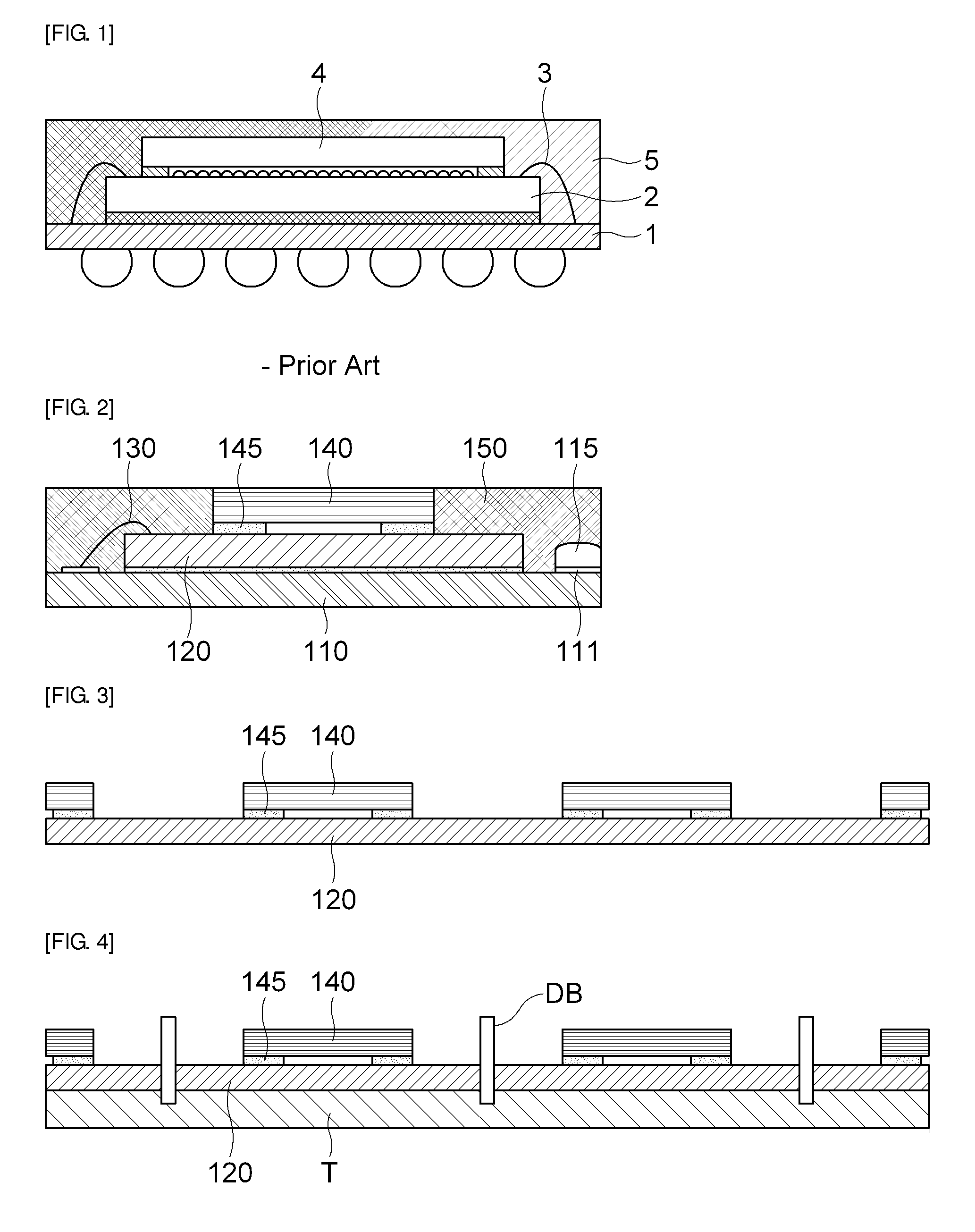
[0064]First of all, FIG. 2 is a schematic cross-sectional view showing a glass cap molding package in accordance with one embodiment of the present invention and a glass cap molding package and a manufacturing method thereof in accordance with one embodiment of the present invention will be described in detail with reference to FIG. 2.

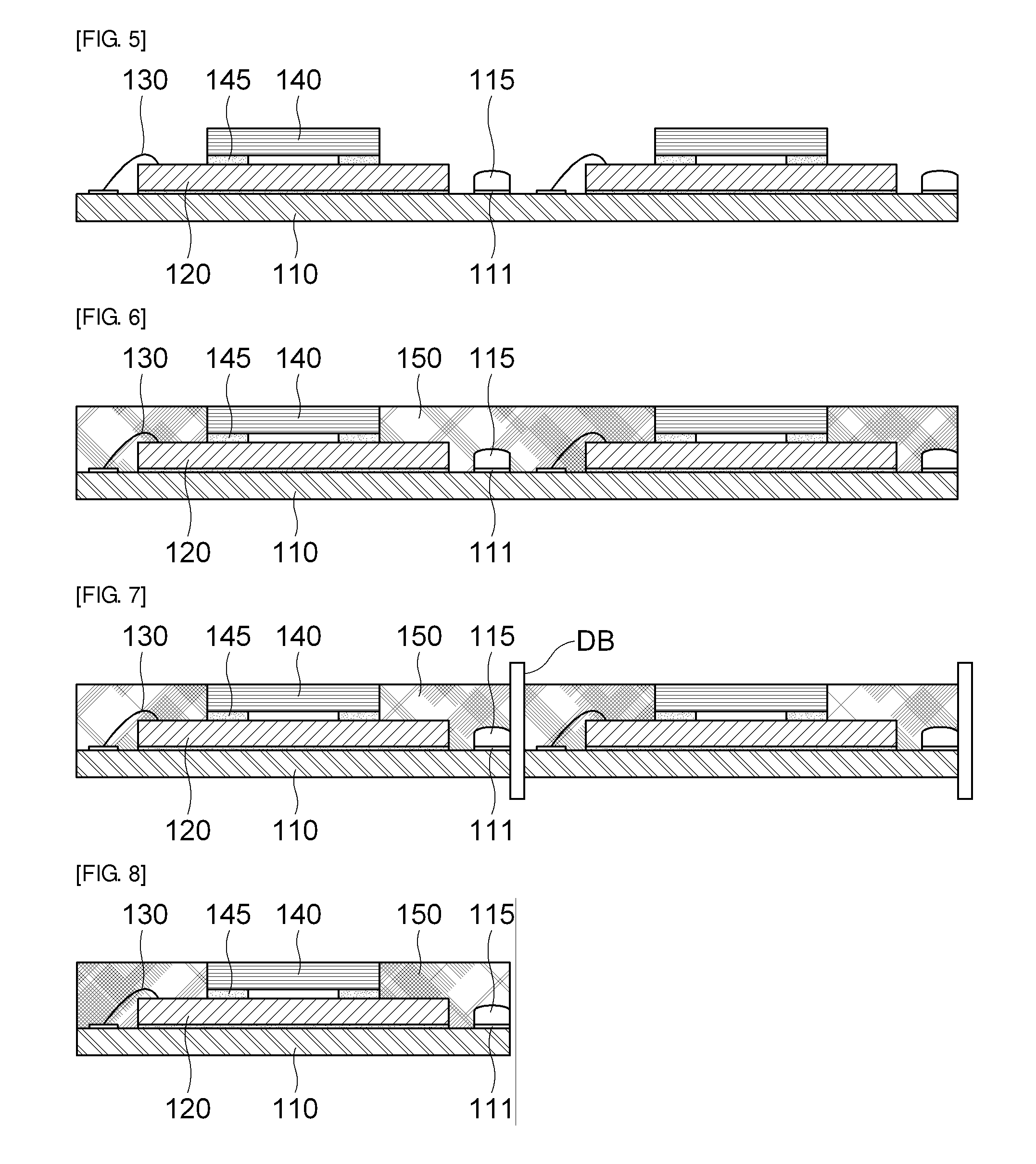
[0065]As shown in FIG. 2, in accordance with the one embodiment of the present invention, the glass cap molding package includes a substrate 110 with an external connection terminal 115 formed on a peripheral region of a top surface, an image sensor 120 mounted on a top surface of the substrate 110, a transparent member 140 installed on an upper part of the image sensor 120, and a molding unit 150 formed to seal the image sensor 120 and the transparent member 140 and exposing the external connection terminal 115 of the substrate 110 to a lateral surface of the substrate 110.

[0066]Herein, passive elements ...

Example

Second Embodiment For a Glass Cap Molding Package

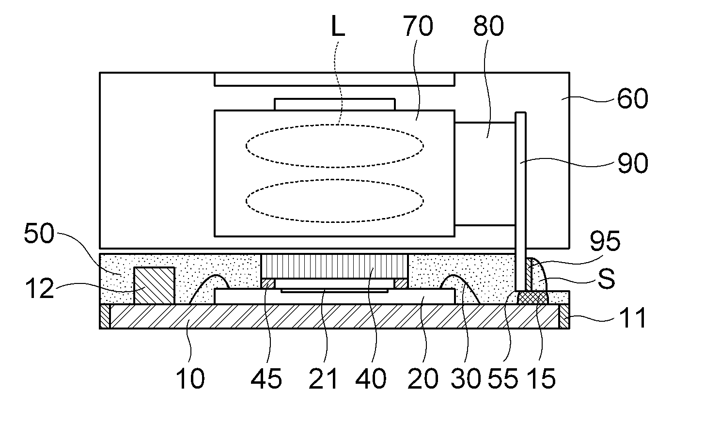
[0084]A glass cap molding package in accordance with embodiments of the present invention will be described in detail with reference to FIG. 9 to FIG. 11.

[0085]FIG. 9 is a schematic cross-sectional view showing a glass cap molding package in accordance with the present invention, FIG. 10 is a plane-view of FIG. 9, and FIG. 11 is a bottom view of FIG. 9.

[0086]As shown in FIG. 9 to FIG. 11, in accordance with the another embodiment of the present invention, the glass cap molding package includes a substrate 10 with an external connection terminal 15 formed on a peripheral region of a top surface, an image sensor 20 mounted on a top surface of the substrate 10, a transparent member 40 installed on an upper part of the image sensor 20, and a molding unit 50 formed to seal the image sensor 20 and the transparent member 40 and having a step unit 55 to expose the external connection terminal 15 of the substrate 10.

[0087]Herein, a passive ele...


PUM


Abstract

The present invention is to reduce a manufacturing cost and improve productivity by manufacturing a small module in comparison with a conventional module and simplifying a process.
In order to achieve the object, the present invention provides a glass cap molding package including a substrate with an external connection terminal formed on a peripheral region of a top surface; an image sensor mounted on the top surface of the substrate; a transparent member installed on an upper part of the image sensor; and a molding unit formed to seal the image sensor and the transparent member and exposing the external connection terminal of the substrate to a lateral surface of the substrate, a manufacturing method thereof and a camera module including the same.

Description

CROSS-REFERENCE TO RELATED APPLICATIONS[0001]This application claims the benefit of Korean Patent Application Nos. 10-2007-0097814 and 10-2008-0044989 filed with the Korea Intellectual Property Office on Sep. 28, 2007 and May 15, 2008, the disclosures of which are incorporated herein by reference.BACKGROUND OF THE INVENTION[0002]1. Field of the Invention[0003]The present invention relates to a glass cap molding package and a camera module including the same; and, more particularly, to a glass cap molding package capable of reducing a manufacturing cost and improving productivity by manufacturing a small module in comparison with a conventional module and simplifying a process, a manufacturing method thereof and a camera module.[0004]2. Description of the Related Art[0005]Nowadays, one of primary trends in the semiconductor business is preferably to downsize a semiconductor device. The need for downsizing is particularly remarkable in the semiconductor chip package business, wherein ...

Claims


Application Information

Patent Timeline
IPC IPC(8): H01L27/146H01L21/00H01L23/02H01L23/28H01L27/14H04N5/335
CPCH01L24/48H01L24/97H01L2224/97H01L2924/1815H01L2924/16235H01L25/50H01L27/14618H01L27/14683H01L2224/48091H01L2924/01078H01L2924/14H01L2924/15311H01L2924/16195H01L2924/00014H01L2224/85H01L2224/73265H01L2924/181H01L2924/00012H01L2224/45099H01L2224/45015H01L2924/207
Inventor RYU, JIN MUNLEE, JUNG SEOKPARK, HYUNG KYUKIM, BO KYOUNGWOO, YUN SEOKKIM, JUNG JIN
Owner SAMSUNG ELECTRO MECHANICS CO LTD
Why Eureka
Try Eureka