Inductor and manufacture method thereof

a manufacturing method and technology of a cylinder head, applied in the direction of magnets, magnet cores/yokes, magnetic bodies, etc., can solve the problem of low efficiency

Active Publication Date: 2009-04-02
CYNTEC
View PDF3 Cites 15 Cited by
  • Summary
  • Abstract
  • Description
  • Claims
  • Application Information

AI Technical Summary

Problems solved by technology

Larger inductors usually have smaller DC resistance, better efficiency, and larger saturation current; smaller inductors have smaller saturation current, occupy less area of printed circuit board, but have larger DC resistance and thus lower the efficiency.

Method used


Image

  • Inductor and manufacture method thereof
  • Inductor and manufacture method thereof
  • Inductor and manufacture method thereof

Examples


Embodiment Construction

[0020]The detailed description of the present invention will be discussed in the following embodiments, which are not intended to limit the scope of the present invention, but can be adapted for other applications. While drawings are illustrated in details, it is appreciated that the scale of each component may not be expressly exactly.

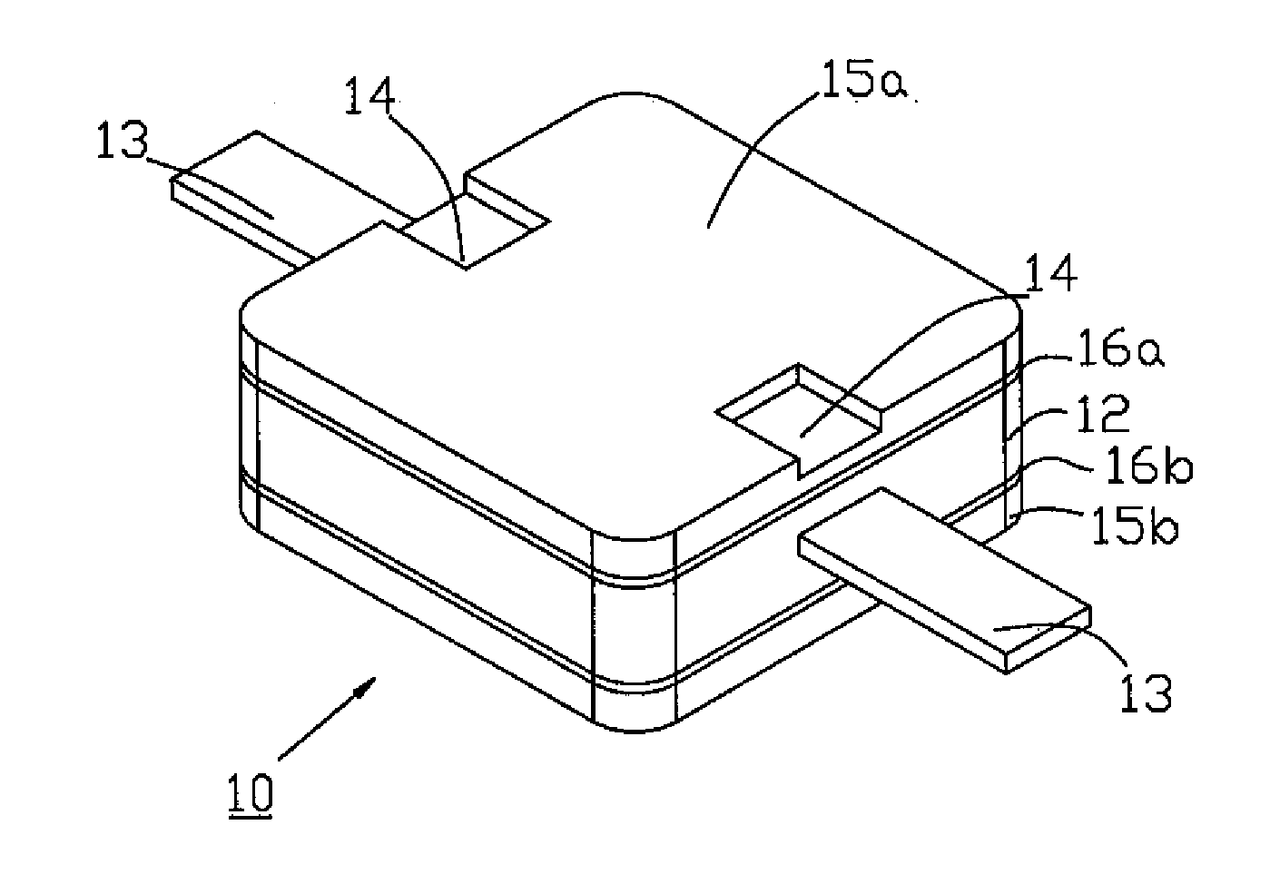
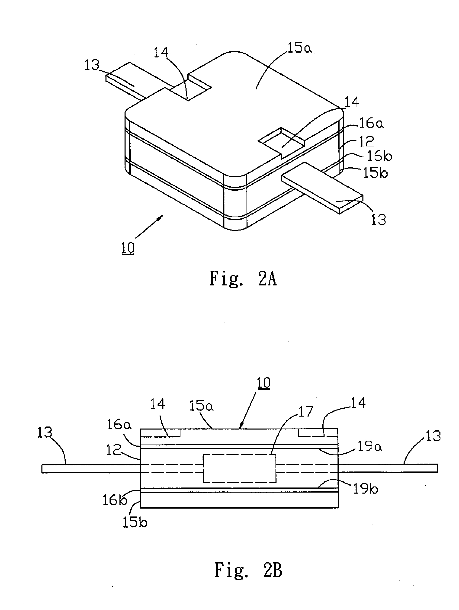
[0021]Referring to FIGS. 2A and 2B, an inductor 10 according to one embodiment of the present invention exemplifies a power inductor (power choke) having high saturation current, but the inductor of the present invention can be other types. The inductor 10 comprises a coil 17, a first magnetic part 12, a second magnetic part 15a / 15b, and two electrodes 13.

[0022]In this embodiment, the coil 17 has a winding structure formed by spirally winding a metal wire having an insulating wrap. In other embodiment, the structure of coil 17 can be other structures such as multi-layer or thin film. The metal wire can be made of gold, copper, or alloys.

[0023]In this ...


PUM

PropertyMeasurementUnit
saturation currentaaaaaaaaaa
thicknessaaaaaaaaaa
thicknessaaaaaaaaaa

Abstract

An inductor comprises a coil, a non-ferrite layer, two electrodes, a first ferrite layer, and a second ferrite layer, where the coil is encapsulated by the non-ferrite layer having a first surface and a second surface opposite to the first surface, two electrodes coupled to the coil are respectively extended out from the non-ferrite layer for connecting a module, and the first ferrite layer and the second ferrite layer are respectively arranged adjacent to the first surface and the second surface of the non-ferrite layer.

Description

FIELD OF THE INVENTION [0001]The present invention relates to a passive component, and more particularly, to an inductor and its manufacture method.DESCRIPTION OF THE PRIOR ART [0002]Inductors play important role in field of passive components. It can steady currents, match impedances, filter currents, store and release energy, harmonize pulses, and form bypass etc. Because electronic products are asked to minimize its size, the size of inductor is inevitably to minimize as well. Not only the size of inductor needs to be small enough to be mounted in a limited printed circuit board, but also the efficiency to match with the printed circuit board should be satisfied.[0003]Generally, three factors are considered to choose an inductor: inductance, saturation current (Isat), and DC resistance (DCR). Larger inductors usually have smaller DC resistance, better efficiency, and larger saturation current; smaller inductors have smaller saturation current, occupy less area of printed circuit ...

Claims


Application Information

Patent Timeline
Patent Type & Authority Applications(United States)
IPC IPC(8): H01F27/29H01F41/00
CPCH01F3/10H01F17/04Y10T29/4902H01F27/29H01F2017/048H01F17/045
Inventor LIU, CHUN-TIAOHUANG, YI-MINHSIEH, ROGERLIAO, CHIN-HSIUNG
Owner CYNTEC
Why Eureka
Try Eureka