Laminated inductor element and manufacturing method thereof

Active Publication Date: 2013-11-28
MURATA MFG CO LTD
View PDF17 Cites 11 Cited by
  • Summary
  • Abstract
  • Description
  • Claims
  • Application Information

AI Technical Summary

Benefits of technology

[0016]Normally, in a plating process, a pre-break mother laminate is swung in a predetermined direction. A plating solution does not stagnate in the grooves provided in the same direction as the swing direction, and thus the diffused metal component is not grown by plating. In the direction perpendicular or substantially perpendicular to the swing direction, however, the plating solution tends to stagnate, and thus the diffused metal component is easily grown by plating. Therefore, it suffices if the non-magnetic layer is thicker than the grooves in the direction perpendicular or substantially perpendicular to the swing direction. Herein, if the grooves provided in the same direction as the swing direction are made deep, and the grooves provided in the direction perpendicular or substantially perpendicular to the swing direction are made shallow, it is possible to reduce the thickness of the non-magnetic layer as much as possible.
[0017]As to the laminated inductor element of a preferred embodiment of the present invention, description is made of a non-limiting example which preferably uses a ferrite c

Problems solved by technology

The laminated element has an issue of warpage caused in the entire element by firing, due to the difference in thermal shrinkage rate among layers.
In a laminated inductor element having a magnetic material formed with coil patterns and laminated, however, different types of materials (magnetic layers and non-magnetic layers, for example) are not allowed to

Method used


Image

  • Laminated inductor element and manufacturing method thereof
  • Laminated inductor element and manufacturing method thereof
  • Laminated inductor element and manufacturing method thereof

Examples


Embodiment Construction

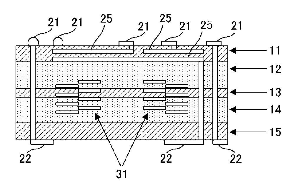
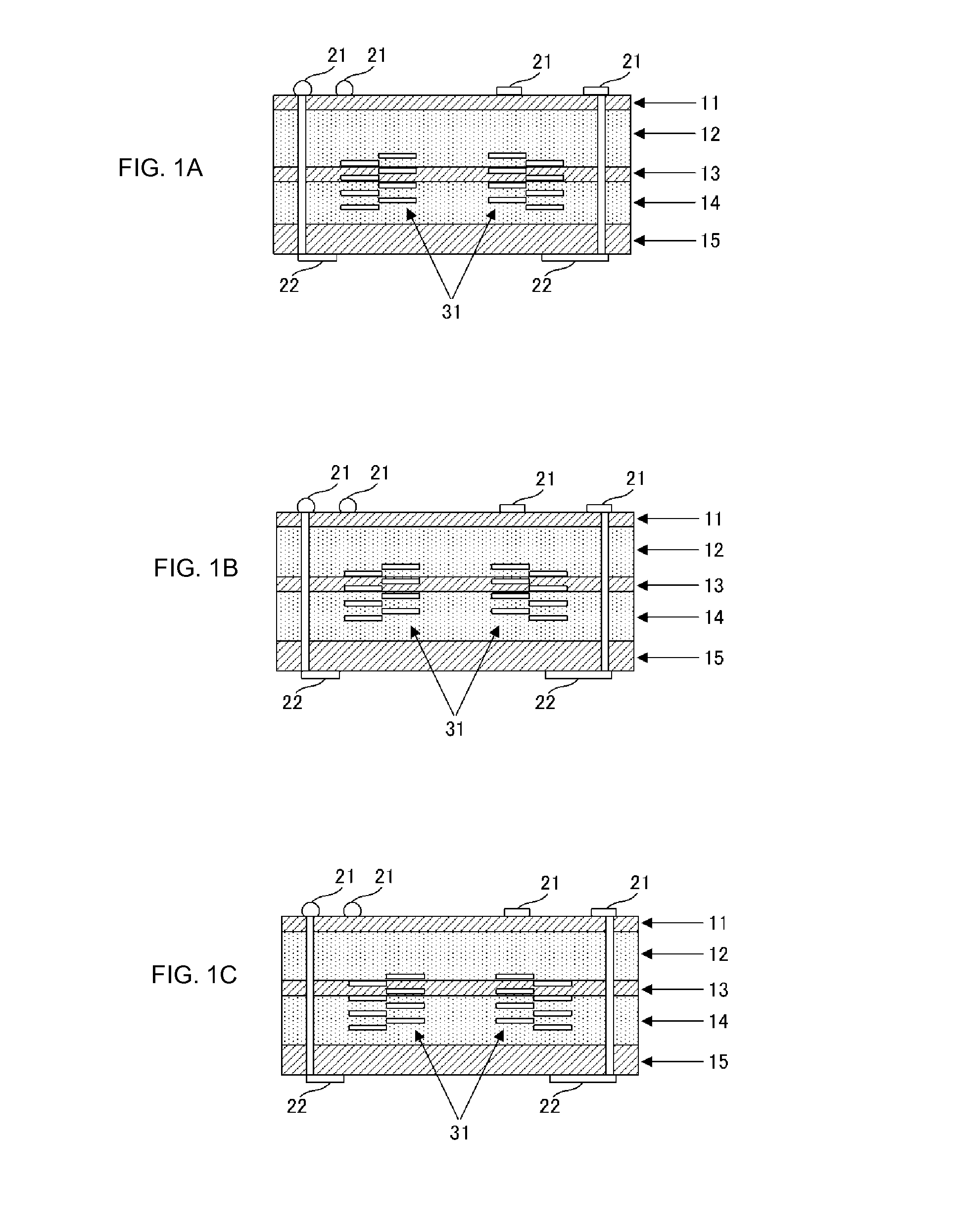
[0027]FIG. 1A is a cross-sectional view of a laminated inductor element according to a preferred embodiment of the present invention. The laminated inductor element is defined by lamination of magnetic ceramic green sheets and non-magnetic ceramic green sheets. In the cross-sectional view illustrated in the present preferred embodiment, the upper side of the drawing corresponds to the upper surface side of the laminated inductor element, and the lower side of the drawing corresponds to the lower surface side of the laminated inductor element.

[0028]The laminated inductor element in the example of FIG. 1A is defined by a laminate having a non-magnetic ferrite layer 11, a magnetic ferrite layer 12, a non-magnetic ferrite layer 13, a magnetic ferrite layer 14, and a non-magnetic ferrite layer 15 sequentially disposed from an outermost layer on the upper surface side toward an outermost layer on the lower surface side.

[0029]On some of the ceramic green sheets defining the laminate, inter...


PUM


Abstract

A laminated inductor element is configured to prevent warpage of the entire element with a structure in which a non-magnetic ferrite layer on an upper surface side is reduced in thickness to achieve a reduction in height of the entire element, a non-magnetic ferrite layer on a lower surface side is increased in thickness to be thicker than the non-magnetic ferrite layer so as to prevent a metal component diffused from a magnetic ferrite layer from coming into electrical contact with a land electrode of a mounting substrate, and an inductor is disposed toward the lower surface side across a non-magnetic ferrite layer.

Description

BACKGROUND OF THE INVENTION[0001]1. Field of the Invention[0002]The present invention relates to a laminated inductor element including a plurality of laminated sheets including a magnetic material and including coil patterns, and to a manufacturing method thereof.[0003]2. Description of the Related Art[0004]In the past, a laminated element having a plurality of laminated sheets has been known. The laminated element has an issue of warpage caused in the entire element by firing, due to the difference in thermal shrinkage rate among layers.[0005]In view of this, Japanese Unexamined Patent Application Publication No. 2004-235374, for example, describes a laminated element having different types of materials alternately laminated to improve the flatness.[0006]Further, Japanese Unexamined Patent Application Publication No. 2009-152489 indicates that a substantially thin low dielectric layer (glass) is disposed on an outermost layer on the mounting surface side to prevent the warpage.[00...

Claims


Application Information

Patent Timeline
IPC IPC(8): H01F17/00
CPCH01F17/0013H01F41/046H01F2017/0066
Inventor SATO, TAKAKO
Owner MURATA MFG CO LTD
Why Eureka
Try Eureka