
Active noise control using bass management

a technology of active noise control and bass management, applied in the direction of noise generation, ear treatment, instruments, etc., can solve the problems of destructive interference, inability to achieve reasonable technical implementation, and inability to yield the desired effect, etc., to achieve the effect of enhancing the active noise control system

Active Publication Date: 2009-04-02
APPLE INC
View PDF26 Cites 115 Cited by
  • Summary
  • Abstract
  • Description
  • Claims
  • Application Information

AI Technical Summary

Benefits of technology

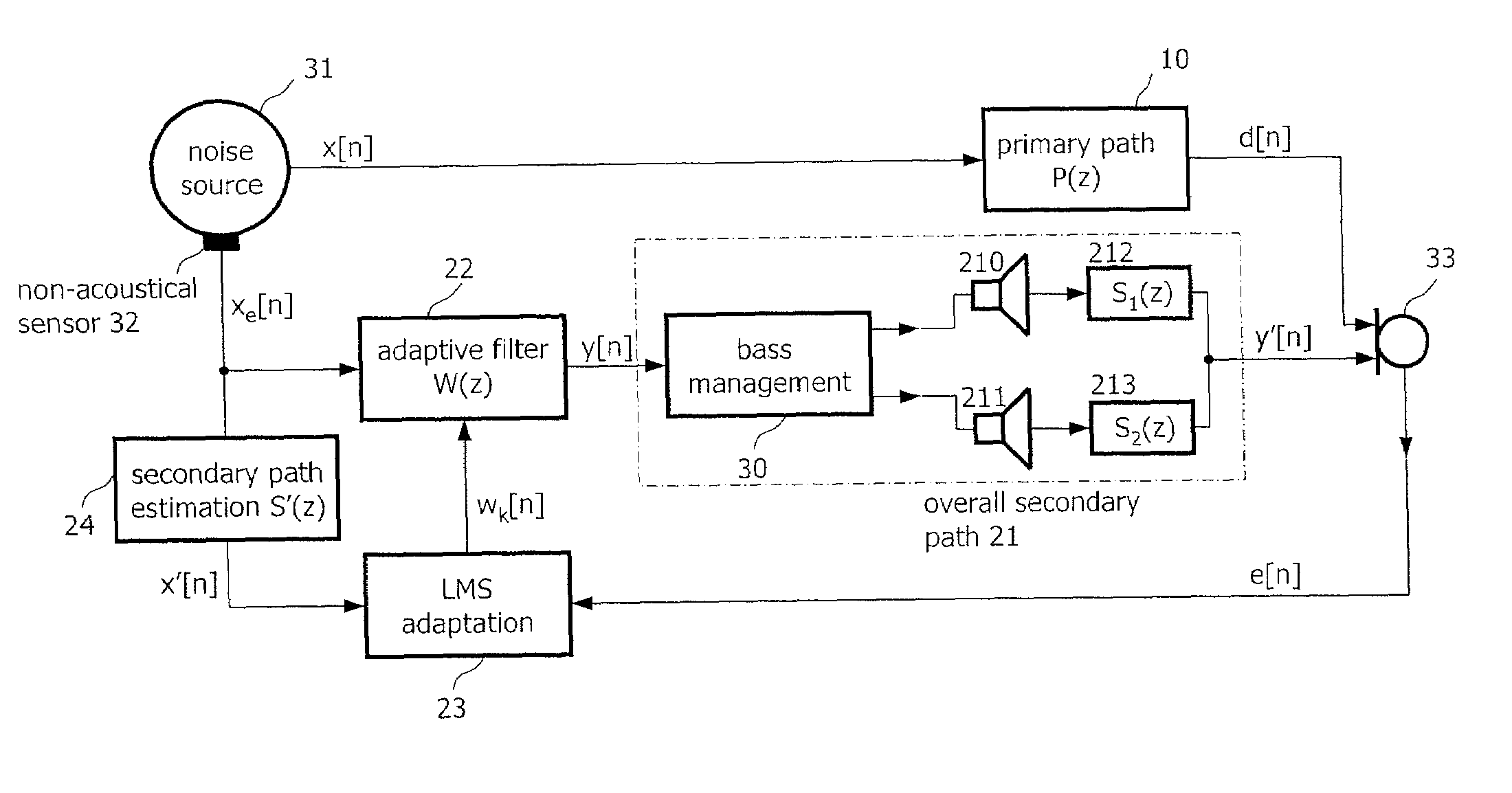
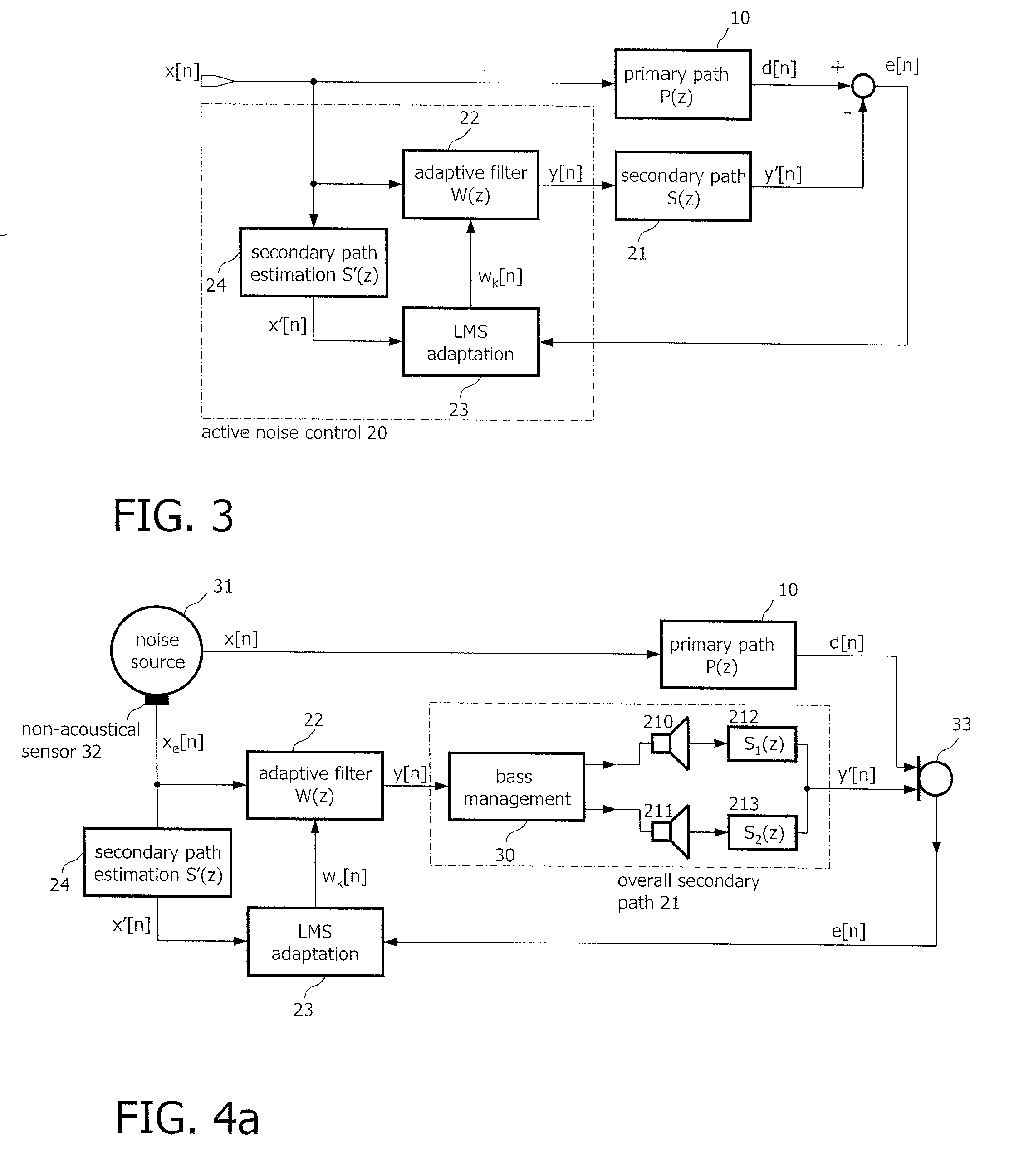
[0012]According to an aspect of the invention, an active noise cancellation system reduces, at a listening position, the power of a noise signal being radiated from a noise source to the listening position. The system includes an adaptive filter that receives a reference signal representing the noise signal, and provides a compensation signal. A bass management unit receives the compensation signal and applies a phase shift to the compensation signal to provide a phase shifted compensation signal. A first acoustic radiator receives the phase shifted compensation signal and radiates audio indicative thereof to the listening position. A second acoustic radiator receives the compensation signal and radiates audio indicative thereof to the listening position. The transfer function characteristics from the input of the bass management system to the listening position approximately matches a desired transfer function.

Problems solved by technology

However, in many applications these efforts do not yield the desired effect of reducing the noise level in a listening room below an acceptable limit.
Although it is known that points of silence can be achieved in a listening room by superposing a compensation sound signal and the noise signal to be suppressed, such that they destructively interfere.
However, a reasonable technical implementation has not been feasible until the development of high performance digital signal processors.
However, the secondary path transfer function is generally unknown and has to be a-priori estimated from measurements.

Method used


Image

  • Active noise control using bass management
  • Active noise control using bass management
  • Active noise control using bass management

Examples


Embodiment Construction

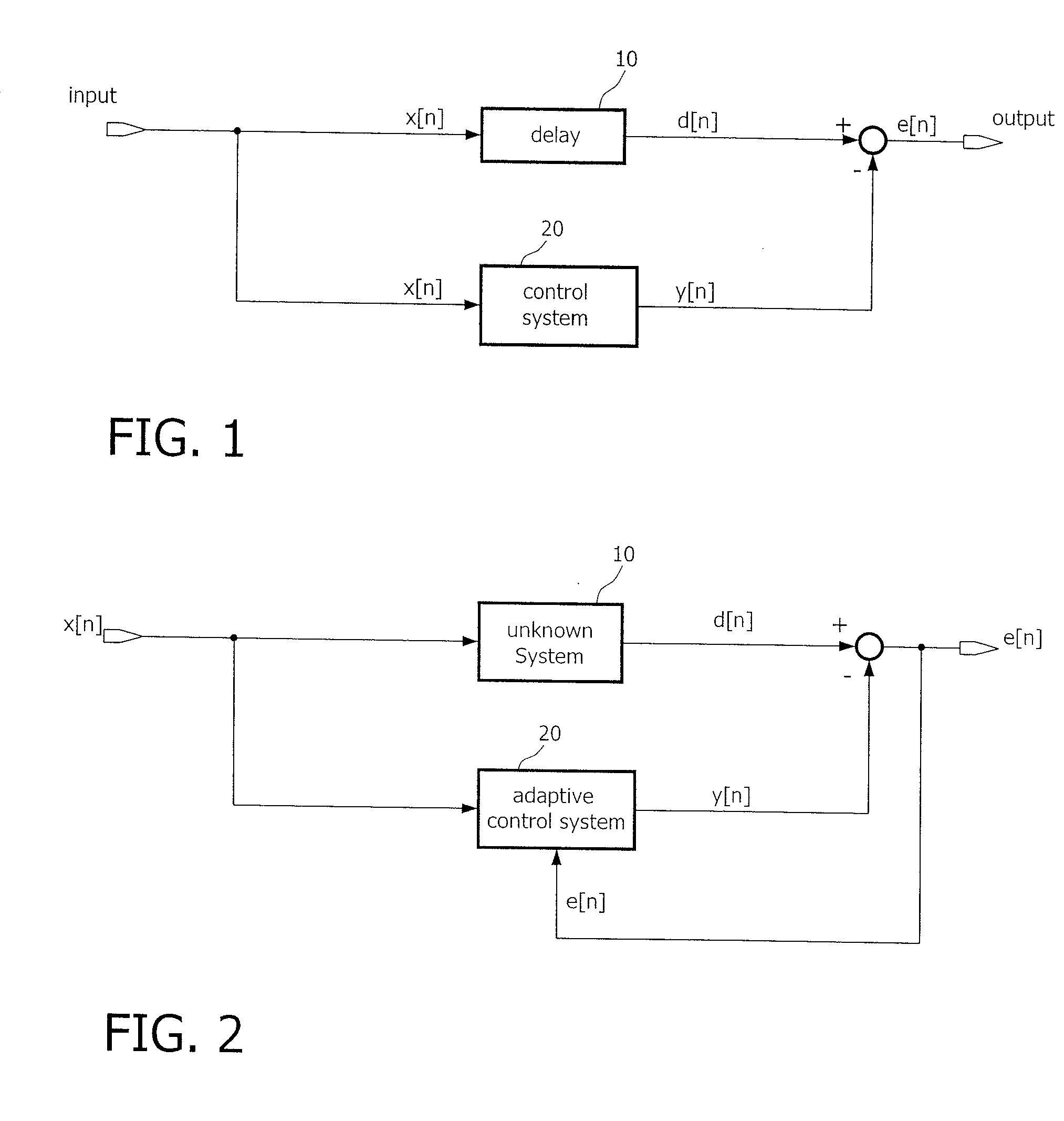
[0027]Active noise control systems may either be implemented as feed-forward structures or as feed-back structures. In a feed-forward structure the acoustic actuator, which generally is a loudspeaker or a set of loudspeakers, is supplied with a signal correlated with the disturbing noise signal that is to be suppressed. In contrast, in a feed-back structure the respective error signal is fed back to the loudspeaker. Feed-forward structures may be preferred for active noise control because they are easier to handle than feedback systems. The following discussion considers mainly ANC systems with a feed-forward structure, however the present invention is also applicable to active noise control systems realized in a feed-back structure. Furthermore, in the figures all signals are regarded as digital signals. Analog-to-digital and digital-to-analog converters as well as amplifiers which are necessary in practice, for example, for sensor signal amplification, are not depicted in the foll...


PUM


Abstract

An active noise cancellation system reduces, at a listening position, the power of a noise signal being radiated from a noise source to the listening position. The system includes an adaptive filter that receives a reference signal representing the noise signal, and provides a compensation signal. A bass management unit receives the compensation signal and applies a phase shift to the compensation signal to provide a phase shifted compensation signal. A first acoustic radiator receives the phase shifted compensation signal and radiates audio indicative thereof to the listening position. A second acoustic radiator receives the compensation signal and radiates audio indicative thereof to the listening position. The transfer function characteristics from the input of the bass management system to the listening position approximately matches a desired transfer function.

Description

CROSS REFERENCE TO RELATED APPLICATIONS[0001]This application contains subject matter related to commonly assigned application serial number TBA, entitled “Automatic Bass Management” filed even-date herewith via EFS-web and designated Attorney docket number 2000-0024. This application is hereby incorporated by reference.CLAIM OF PRIORITY[0002]This patent application claims priority to European Patent Application serial number 07 019 092.1 filed on Sep. 27, 2007 and European Patent Application serial number 08 001 742.9 filed on Jan. 30, 2008.FIELD OF THE INVENTION[0003]The present invention relates to active noise control and to a bass management system for equalizing the sound pressure level in the low frequency (bass) range in order to approach a desired sound pressure level target function.RELATED ART[0004]Disturbing Noise, in contrast to a useful sound signal, is sound that is not intended to meet a certain receiver (e.g., a listener's ears). Generally the process of generating ...

Claims


Application Information

Patent Timeline
Patent Type & Authority Applications(United States)
IPC IPC(8): G10K11/16
CPCH04R3/04H04S7/302H04R2499/13
Inventor CHRISTOPH, MARKUS
Owner APPLE INC
Learn More