Charging device

Inactive Publication Date: 2009-04-02
CANON KK
View PDF5 Cites 13 Cited by
  • Summary
  • Abstract
  • Description
  • Claims
  • Application Information

AI Technical Summary

Benefits of technology

[0009]A principal object of the present invention is to provide a cleaning device capable of stably retaining chargi

Problems solved by technology

As a factor of a lowering in service life of the charging roller, there is charging roller contamination by transfer of contaminants, such as external additives added to toner and toner itself, from the photosensitive member.
Such charging roller contamination leads to a lowering in charging power or charging non-uniformity.
However, in the case of the charging roller on which the grain of polish trace is formed, the charging roller cannot be cleaned sufficiently by the above-described cleaning pad.
Specifically, the above-described contaminants such as external additives and the like are liable to remain

Method used


Image

  • Charging device
  • Charging device
  • Charging device

Examples


experimental example 1

1) Preparation of Charging Roller 2

[0154]A rubber composition was prepared by using the following ingredients as materials for forming the electroconductive elastic layer 22.

Epichlorohydrin rubber100wt. partsLiquid polychloroprene6wt. partsThiourea compound2wt. partsSulfur0.3wt. part

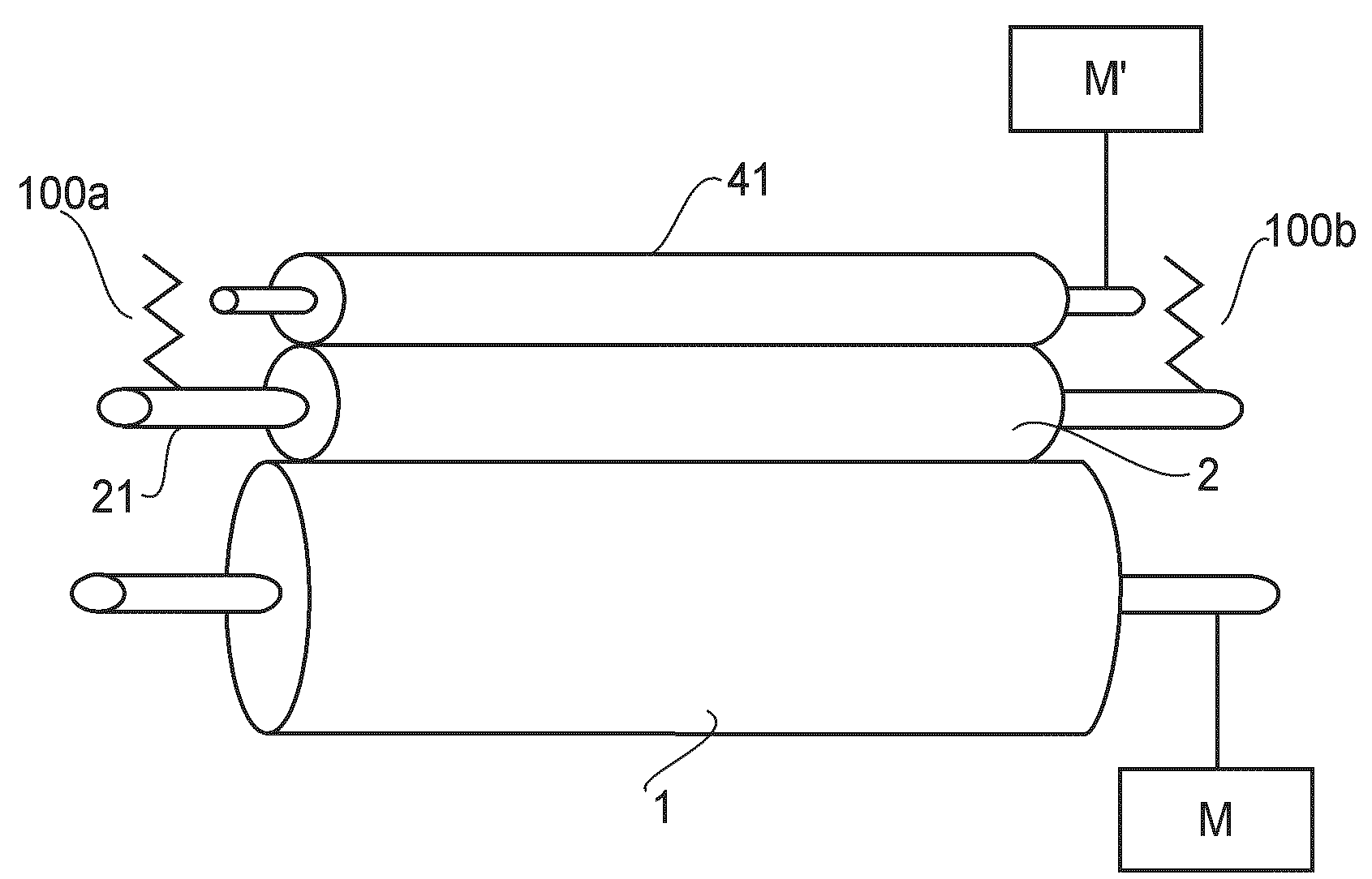
[0155]After an adhesive was applied onto an outer peripheral surface of a core metal (rotatable shaft) 11 consisting of a metal shaft having a diameter of 8 mm, the core metal 11 was set in a metal mold for forming a roller and kept at 70° C. Into the metal mold, the above-prepared rubber composition was injected, followed by reaction and curing for about 10 minutes to obtain the electroconductive elastic layer 22 as a base material for the charging roller 2. The resultant roller structure was removed from the metal mold and aged for about 24 hours at room temperature. A diameter of the roller structure was 15 mm. This roller structure was subjected to surface polishing by a polishing machine to obtain a...

experimental example 2

1) Preparation of Charging Roller 2

[0177]The charging roller 2 prepared in Experimental Example 1 was, after being polished, subjected to surface treatment with the following surface treating liquid.

[0178]The surface treating liquid was prepared by dispersing and mixing the following ingredients in a ball mill for 3 hours.

Ethyl acetate100wt. partsIsocyanate compound20wt. partsAcethylene black5wt. partsAcrylicsilicone polymer1wt. part

[0179]While this surface treating liquid was kept at 23° C., the charging roller 2 prepared in Experimental Example 1 was dipped in the surface treating liquid for 10 seconds and heated for 1 hour in an oven kept at 120° C. to prepare a charging roller 2 treated with the surface treating liquid.

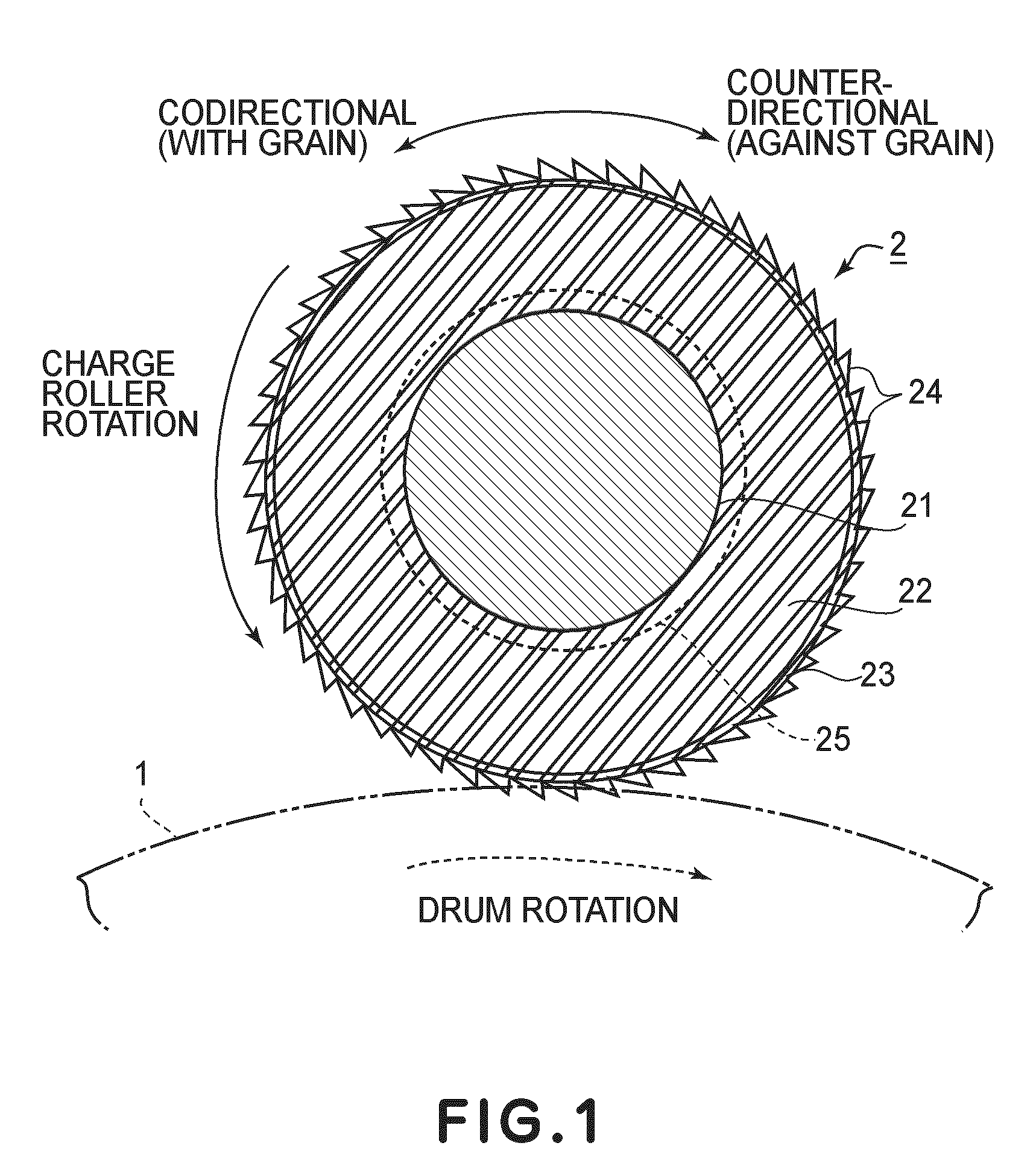
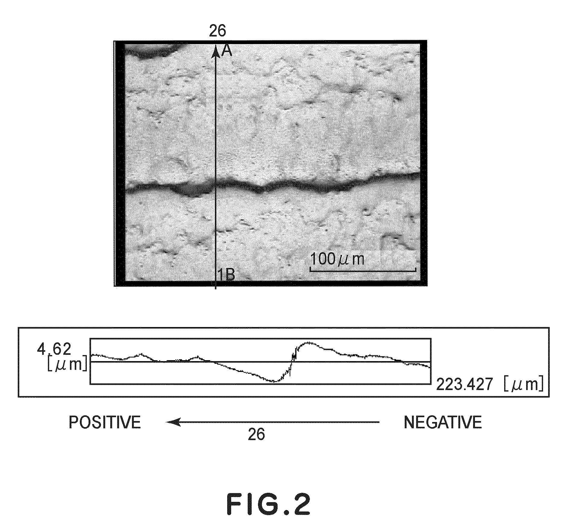
[0180]This charging roller 2 was provided with grain of polish trace 24 having a surface roughness (Rz) of 8 μm, a stepped portion length (height) 36 of 7 μm, a width 35 of the grain of polish trace 24 of 170 μm, θ1 of 70 degrees, and θ2 of 2 degrees.

2) Preparatio...

experimental example 3

1) Preparation of Charging Roller 2

[0186]With respect to the charging roller 2 prepared in Experimental Example 1, the ingredients for a rubber portion (electroconductive elastic layer 22) were changed to those shown below.

Polyurethane polymer100wt. partsLithium perchlorate1wt. partsDibutyltin dilaurate0.01wt. partElectroconductive carbon (Electroconductive agent)25wt. partsDicumyl peroxide (Cross-linking agent)0.5wt. part

[0187]These ingredients were caused to react with 4,4′-diphenylmethane diisocyanate (MDI) for 12 hours at 100° C. to obtain a prepolymer including the electroconductive agent and the cross-linking agent.

[0188]This prepolymer was used as the molding material and was subjected to polishing by using the same metal mold as in Experimental Example 1 in the same manner as in Experimental Example 1 except that the rotational speed for polishing was changed to half of that in Experimental Example 1.

[0189]A charging roller 2 provided with grain of polish trace was prepared ...


PUM


Abstract

A charging device includes a charging roller for electrically charging a photosensitive member. The charging roller alternately has pits and projections along a circumferential direction thereof. The projections project in an inclined direction in which the projections are inclined with respect to a radial direction of the charging roller. The charging device further includes a roller rotating mechanism for rotating the charging roller to provide a peripheral movement thereof in a sense from the radial direction toward the inclined direction, a brush for cleaning the charging roller, and a brush rotating mechanism for rotating the brush to provide a peripheral movement thereof counterdirectionally with the inclined direction at a position in which the brush and the charging roller contact each other.

Description

FIELD OF THE INVENTION AND RELATED ART[0001]The present invention relates to a charging device for use in an image forming apparatus such as a copying machine, a printer, a facsimile machine, or a multi-function machine having a plurality of functions of these machines.[0002]In a conventional electrophotographic image forming apparatus, a photosensitive member is uniformly charged electrically by using a charging roller disposed so as to be rotated by the photosensitive member. Specifically, the photosensitive member is electrically charged by applying a superposed charging bias of a DC voltage and an AC voltage to a core metal of the charging roller to utilize an electric discharge phenomenon occurring in the neighborhood of a contact portion between the charging roller and the photosensitive member.[0003]In recent years, with improvement in image forming speed of the image forming apparatus, service life extension of various devices is desired, so that the service life extension i...

Claims


Application Information

Patent Timeline
IPC IPC(8): G03G15/02
CPCG03G15/0225G03G2215/025G03G15/0233
Inventor OGURA, MOTOHIRO
Owner CANON KK
Why Eureka
Try Eureka