Pattern identification method, parameter learning method and apparatus

a parameter learning and pattern identification technology, applied in knowledge representation, instruments, computing models, etc., can solve problems such as unsatisfactory conventional techniques as described above, and achieve the effect of high speed and high accuracy

Active Publication Date: 2009-04-02
CANON KK
View PDF15 Cites 28 Cited by
  • Summary
  • Abstract
  • Description
  • Claims
  • Application Information

AI Technical Summary

Benefits of technology

[0007]The present invention has been conceived in light of the foregoing, and it is an object of the present invention to achieve a pattern identification process for identifying input data that belongs to either of two classes with high speed and high accuracy.

Problems solved by technology

However, conventional techniques as described above are not satisfactory.

Method used


Image

  • Pattern identification method, parameter learning method and apparatus
  • Pattern identification method, parameter learning method and apparatus
  • Pattern identification method, parameter learning method and apparatus

Examples


embodiment 1

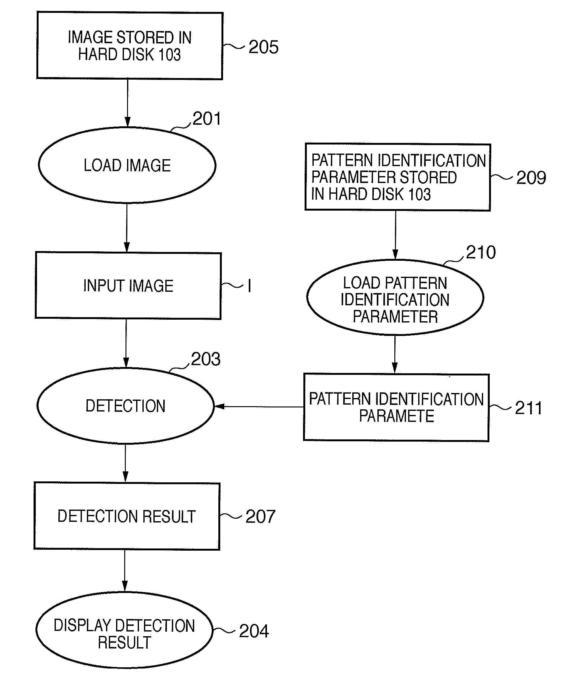
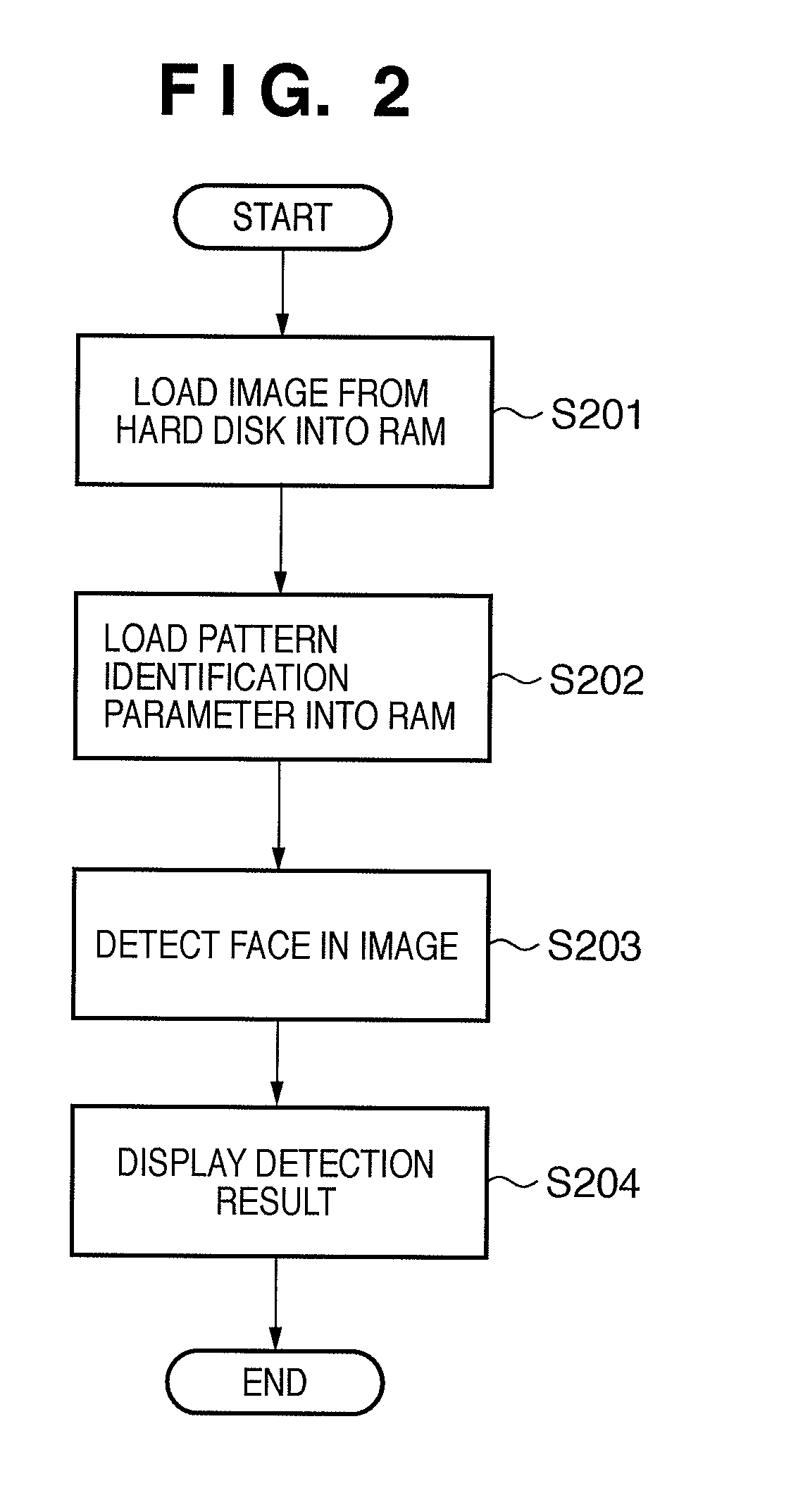
[0055]Embodiment 1 illustrates an example of an information processing apparatus that determines whether or not an input image includes a face. In order to simplify the description of the present embodiment, it is assumed that, if a face is included in inputted images, the face has a predetermined size and is arranged at a substantially center position, as in passport photographs. It is, of course, possible to detect a face of any size that is located at any position by scanning or enlarging / reducing an image.

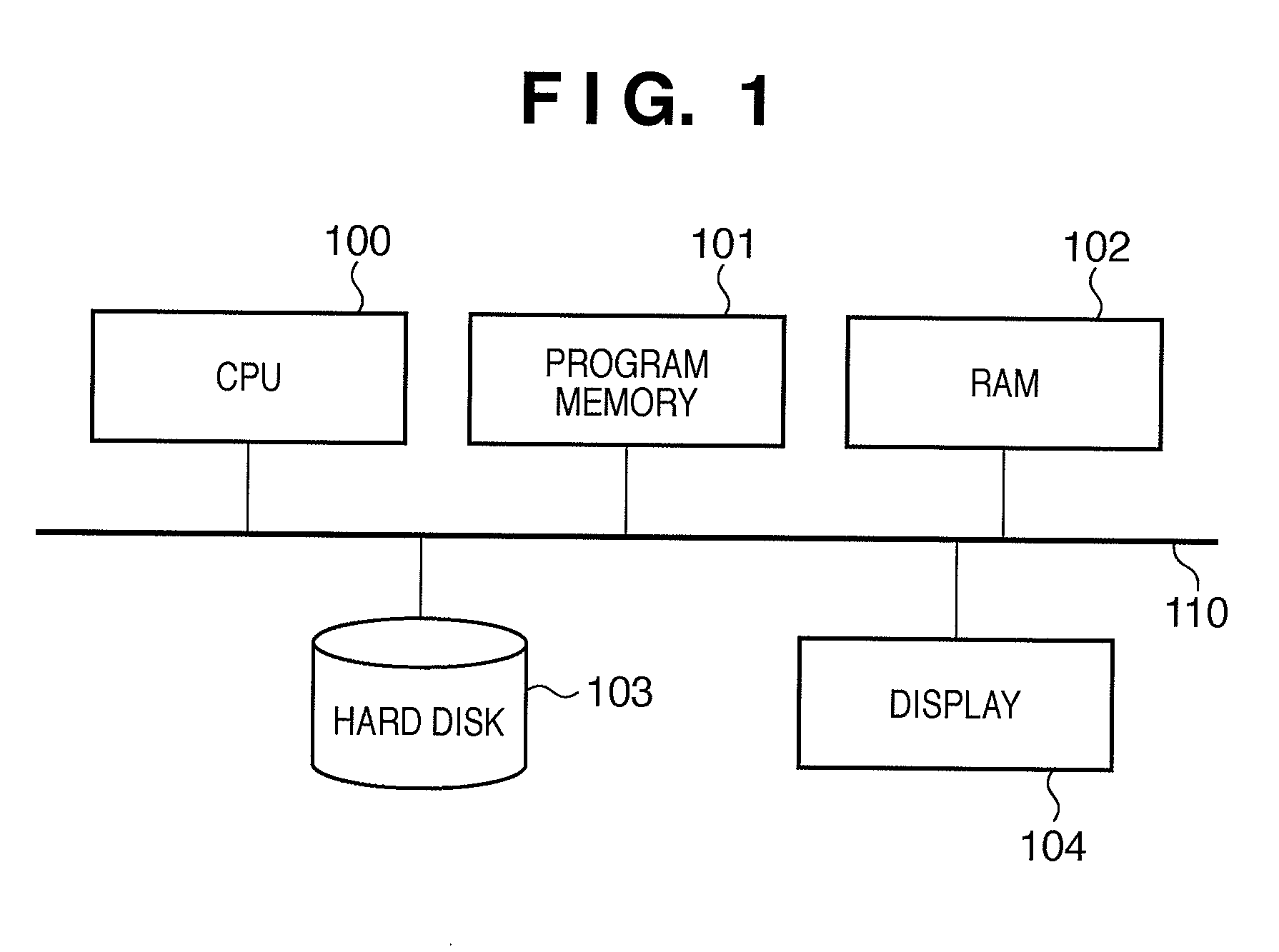
[0056]FIG. 1 is a block diagram used to illustrate an example of the hardware configuration of an information processing apparatus according to Embodiment 1. In FIG. 1, reference numeral 100 denotes a CPU (central processing unit), which executes an information processing method described in the present embodiment in accordance with a program. Reference numeral 101 denotes a program memory, which stores programs that are executed by the CPU 100. Reference numeral 102 denotes a ...

embodiment 2

[0080]Embodiment 2 illustrates an example of an information processing apparatus that detects an object having a specific texture from an inputted image. Unlike Embodiment 1, in Embodiment 2, an object to be detected may not be located in a predetermined location of an input image. Furthermore, in Embodiment 1, a set of rectangles groups needs to be determined in advance, whereas in Embodiment 2, rectangles groups that are used by respective nodes for identification processing are automatically generated by preparing only rectangles that serve as candidates for elements, and setting the number of rectangles included in a single rectangles group. For the sake of simplicity, Embodiment 2 describes a binary tree, but it is easily conceivable from Embodiment 1 that the present embodiment can be applied to a multiway tree.

[0081]The information processing apparatus according to Embodiment 2 has the same hardware configuration as that of Embodiment 1 (FIG. 1). Accordingly, reference should...


PUM


Abstract

In a pattern identification method in which input data is classified into predetermined classes by sequentially executing a combination of a plurality of classification processes, at least one of the classification processes includes a mapping step of mapping the input data in an N (N≧2) dimensional feature space as corresponding points, a determination step of determining whether or not to execute the next classification process based on the corresponding points, and selecting step of selecting a classification process to be executed next based on the corresponding points when it is determined in the determination step that the next classification process should be executed.

Description

BACKGROUND OF THE INVENTION[0001]1. Field of the Invention[0002]The present invention relates to a parameter learning method for identifying a pattern of an input signal, such as image recognition, and a pattern identification method using the same.[0003]2. Description of the Related Art[0004]Many techniques have heretofore been conceived as a pattern identification method for classifying input data into predetermined classes, such as character recognition, face detection and gait authentication, and various new techniques are still being proposed with the goal of increasing the processing speed and improving the classification accuracy. For example, Viola & Jones (2001) “Rapid Object Detection using a Boosted Cascade of Simple Features”, Computer Vision and Pattern identification (hereinafter Document 1) proposes to achieve a high-speed and highly accurate pattern identification method by combining a learning method based on AdaBoost and a technique for cascade-connecting weak clas...

Claims


Application Information

Patent Timeline
Patent Type & Authority Applications(United States)
IPC IPC(8): G06N5/02G06V10/764G06V10/75
CPCG06K9/68G06K9/6282G06V10/75G06V10/764G06F18/24323
Inventor TORII, KANMORI, KATSUHIKOMITARAI, YUSUKESATO, HIROSHIKANEDA, YUJISUZUKI
Owner CANON KK
Why Eureka
Try Eureka