
Volumetric Efficiency Based Lift Pump Control

a technology of efficiency and lift pump, applied in the direction of pump control, fuel injection apparatus, charge feed system, etc., can solve the problems of degrading engine performance, difficult selection of operating and control parameters of lower pressure fuel pumps, inaccurate control of lower pressure pumps, etc., to maintain the efficiency of higher pressure fuel pumps

Inactive Publication Date: 2009-04-09
FORD GLOBAL TECH LLC
View PDF9 Cites 51 Cited by
  • Summary
  • Abstract
  • Description
  • Claims
  • Application Information

AI Technical Summary

Benefits of technology

[0004]In contrast, or in addition, to the above approach, the inventor has recognized that the control objective should not necessarily be to enforce a minimum pressure of the lower pressure fuel pump, but instead should be to operate the lower pressure fuel pump to provide just enough power (e.g. fuel volume flow and fuel pressure increase) to provide a target efficiency for the higher pressure fuel pump. Since the higher pressure fuel pump is typically operated to provide a greater fuel pressure increase than the lower pressure fuel pump, inefficiencies in the higher pressure pump can be of greater detriment to fuel economy than inefficiencies in the lower pressure fuel pump. Therefore, the lower pressure fuel pump can be provided with just enough power so that the higher pressure fuel pump can achieve a minimum volumetric efficiency, thereby increasing the overall fuel economy of the engine system.
[0007]In this way, operation of the lower pressure and higher pressure fuel pumps can be coordinated to provide the prescribed fuel pressure and volumetric flow rate of fuel to the engine, while also maintaining the efficiency of the higher pressure fuel pump to at least a prescribed level.

Problems solved by technology

The inventor herein has recognized that selecting the operating and control parameters of the lower pressure fuel pump can be difficult due to the various competing considerations and requirements of the fuel delivery system.
However, if the lower pressure fuel pump is operated to supply too little fuel pressure to the higher pressure fuel pump, the higher pressure fuel pump may be provided with fuel vapor, which can degrade engine performance.
However, if the fuel delivery system does not include a pressure sensor between the lower pressure pump and the higher pressure pump for providing fuel pressure feedback, control of the lower pressure pump may be inaccurate.
Even if a pressure sensor was provided between the lower pressure pump and the higher pressure pump, sensor delays and sensor degradation may still result in inaccuracies in the lower pressure pump control.
Furthermore, the addition of the fuel pressure sensor between the lower pressure fuel pump and the higher pressure fuel pump may add cost and complexity to the fuel delivery system.
Since the higher pressure fuel pump is typically operated to provide a greater fuel pressure increase than the lower pressure fuel pump, inefficiencies in the higher pressure pump can be of greater detriment to fuel economy than inefficiencies in the lower pressure fuel pump.

Method used


Image

  • Volumetric Efficiency Based Lift Pump Control
  • Volumetric Efficiency Based Lift Pump Control
  • Volumetric Efficiency Based Lift Pump Control

Examples


Embodiment Construction

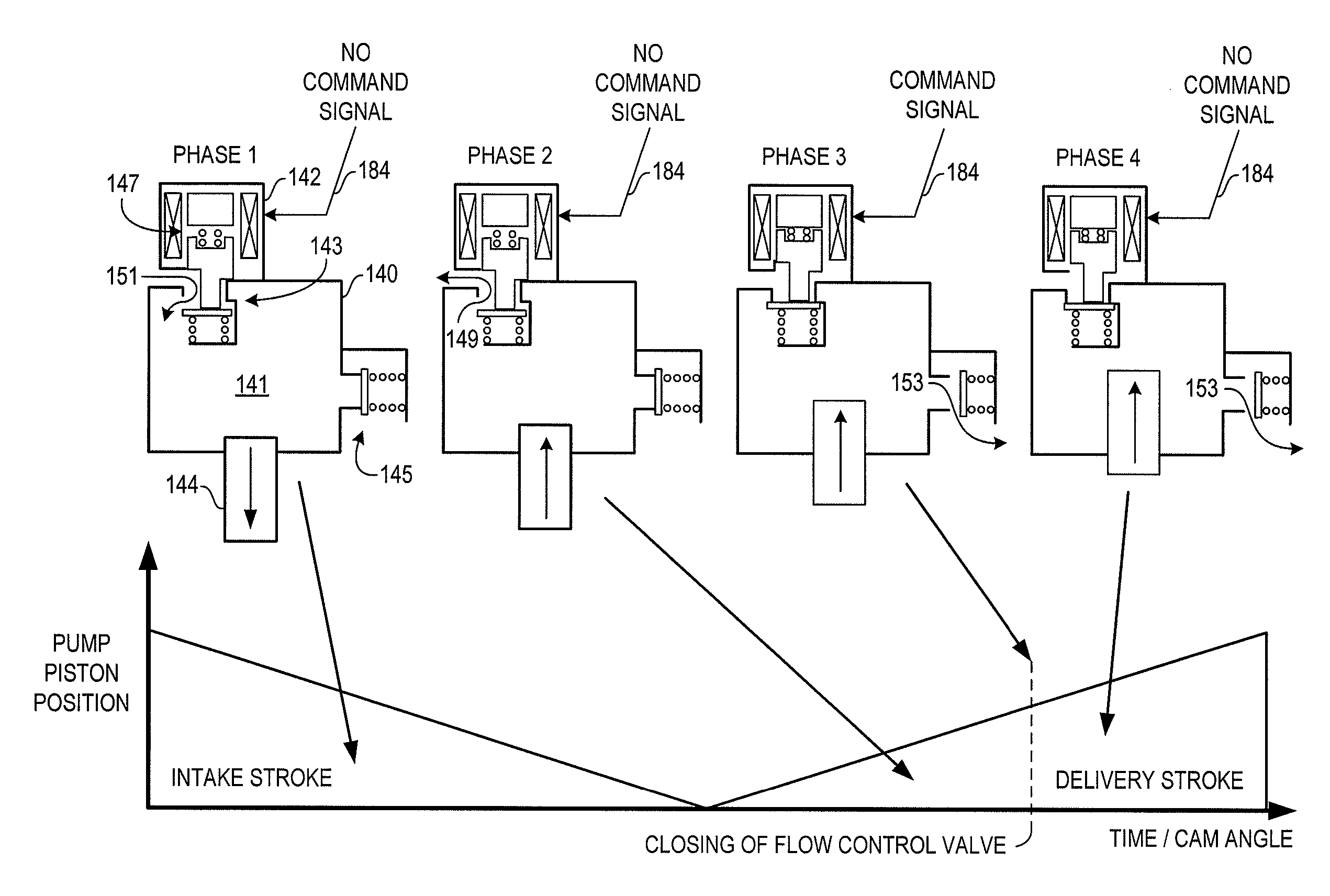
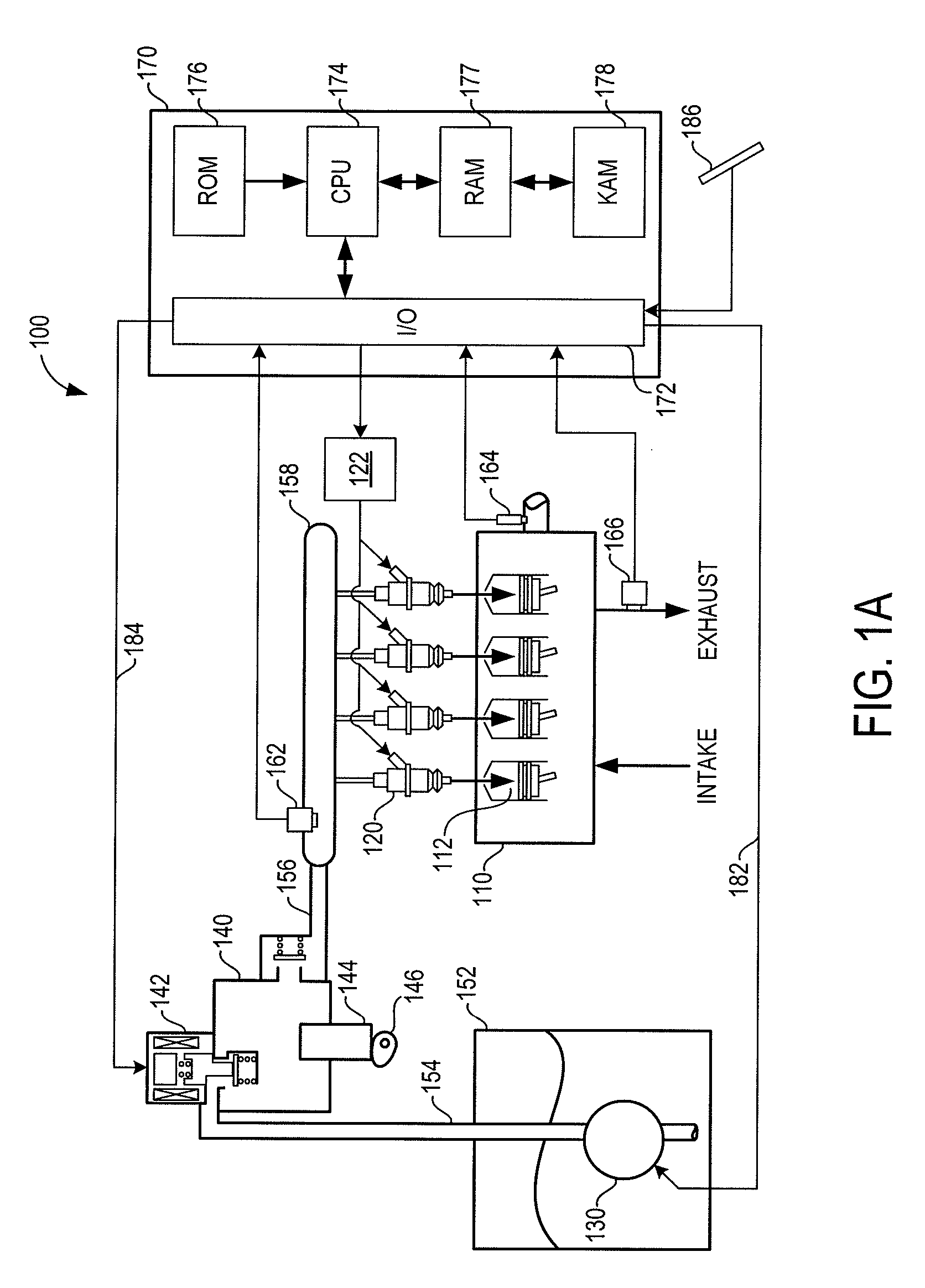
[0013]FIG. 1A shows an engine system 100, which may be configured as a propulsion system for a vehicle. Engine system 100 includes an internal combustion engine 110 having multiple combustion chambers or cylinders 112. Fuel can be provided directly to cylinders 112 via in-cylinder direct injectors 120. As indicated schematically in FIG. 1A, engine 110 can receive intake air and exhaust products of the combusted fuel. Engine 110 may include an suitable type of engine including a gasoline or diesel engine.

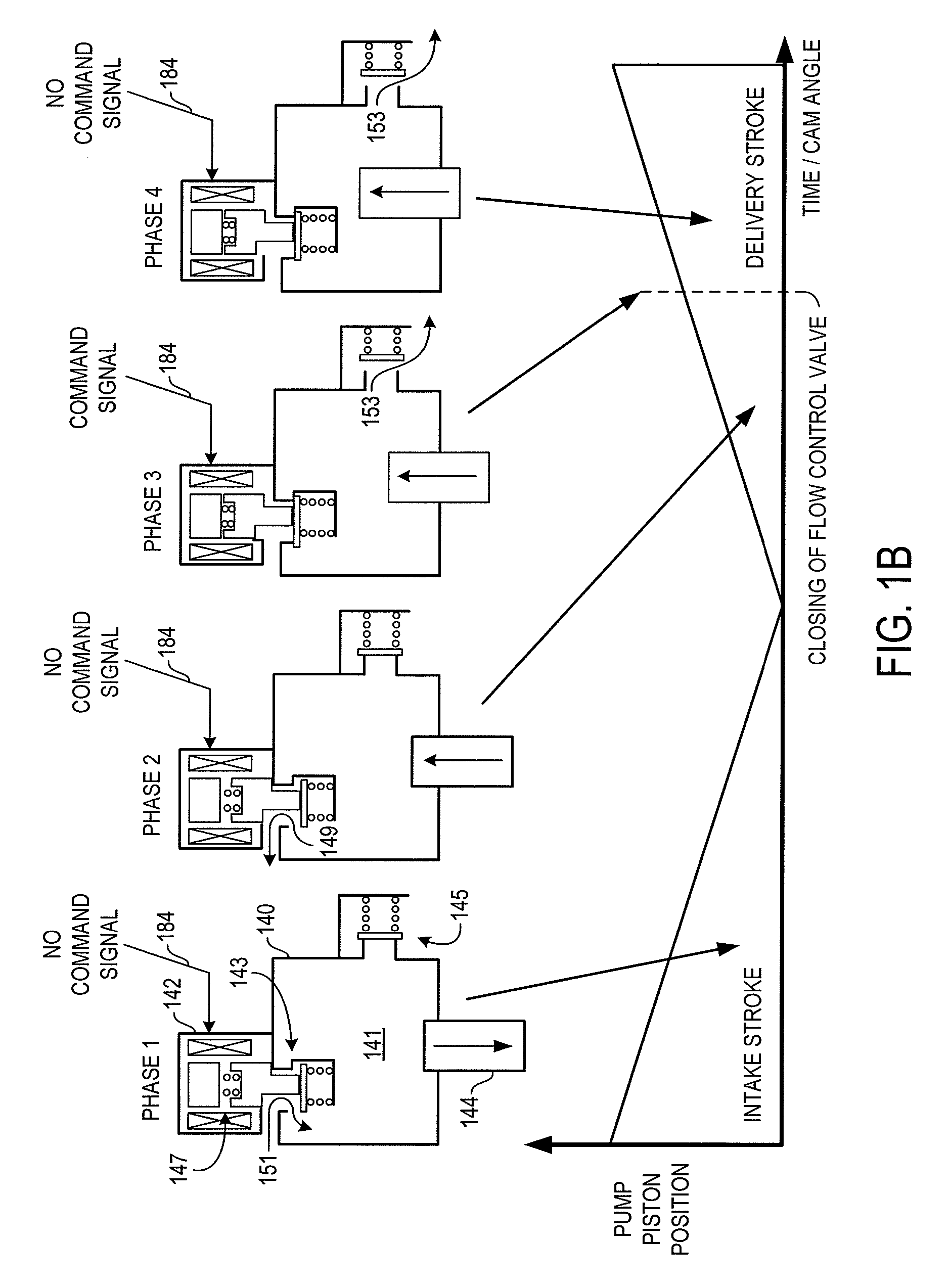
[0014]Fuel can be provided to engine 110 via injectors 120 by way of a fuel system indicated generally at 150. In this particular example, fuel system 150 includes a fuel storage tank 152 for storing the fuel on-board the vehicle, a lower pressure fuel pump 130, a higher pressure fuel pump 140, a fuel rail 158, and various fuel passages 154 and 156.

[0015]Lower pressure fuel pump 130 can be operated by a controller 170 to provide fuel to higher pressure fuel pump 140 via fuel passage ...


PUM


Abstract

As one example, a method of operating a fuel delivery system of a directly injected internal combustion engine including a plurality of in-cylinder direct fuel injectors, a higher pressure fuel pump and a lower pressure fuel pump is provided. The method comprises operating the lower pressure fuel pump and the higher pressure fuel pump to maintain a prescribed fuel pressure at the fuel injectors; and varying an amount of pump work that is provided by the lower pressure fuel pump relative to the higher pressure fuel pump responsive to an indication of the efficiency of the higher pressure pump.

Description

BACKGROUND AND SUMMARY[0001]Some vehicle engine systems utilizing direct in-cylinder injection of fuel include a fuel delivery system that has multiple fuel pumps for providing suitable fuel pressure to the fuel injectors. As one example, a fuel delivery system can utilize an electrically driven lower pressure pump (i.e. lift pump) and a mechanically driven higher pressure pump arranged respectively in series between the fuel tank and the fuel injectors. In some cases, the lower pressure pump has been utilized in conjunction with a mechanical return-less fuel system whereby the fuel pressure provided by the lower pressure pump is governed by a mechanical bypass regulator (e.g. set at 65 to 80 psi).[0002]The inventor herein has recognized that selecting the operating and control parameters of the lower pressure fuel pump can be difficult due to the various competing considerations and requirements of the fuel delivery system. For example, if the lower pressure fuel pump is operated t...

Claims


Application Information

Patent Timeline
IPC IPC(8): F02M57/02F02M37/08F04B49/06
CPCF02M37/0058
Inventor PURSIFULL, ROSS DYKSTRA
Owner FORD GLOBAL TECH LLC
Learn More