Fuel Tank Assembly And Associated Method

a technology for fuel tanks and fuel tanks, applied in water supply installation, container discharging methods, transportation and packaging, etc., can solve the problems of fuel tanks carrying aircraft or other vehicles being susceptible to being impacted by ballistic projectiles, damage to fuel tanks, increase the possibility of fire or explosion, etc., to reduce the likelihood of further damage

Inactive Publication Date: 2009-04-09
THE BOEING CO
View PDF4 Cites 18 Cited by
  • Summary
  • Abstract
  • Description
  • Claims
  • Application Information

AI Technical Summary

Benefits of technology

[0007]A fuel tank assembly and associated method are therefore provided according to embodiments of the present invention which may limit the deleterious effect otherwise occasioned by the impact of a ballistic projectile upon a fuel tank. In this regard, the fuel tank assembly and associated method of embodiments of the present invention may limit, if not eliminate, fuel leakage from a fuel tank that may otherwise be produced by the impact of a ballistic projectile with the fuel tank. Additionally, the fuel tank assembly and associated method of embodiments of the present invention may reduce the likelihood of further damage to the fuel tank due to the hydrodynamic ram effect created by the entry of a ballistic projectile within the fuel tank.

Problems solved by technology

In certain circumstances, a fuel tank carried by an aircraft or other vehicle may be susceptible to being impacted by a ballistic projectile.
Alternatively, fragments generated by an uncontained engine failure or the like may also impact the fuel tank of an aircraft or other vehicle and create similar issues.
Regardless of the source of a ballistic projectile, a ballistic projectile can puncture the fuel tank which results not only in damage to the fuel tank, but may also allow fuel to leak from the tank and increase the possibility of a fire or explosion.
Moreover, a ballistic projectile that enters a fuel tank may also create a hydrodynamic ram effect which, in turn, can produce even larger holes and tears in a fuel tank and, accordingly, an even greater risk of fire or other damage.
The resulting pressure wave may then strike the wall of the fuel tank over a relatively large area and, depending upon the magnitude of the pressure wave and the construction of the fuel tank, may create a relatively large hole or tear in the wall of the fuel tank.
However, the additional weight necessitated by the armor is disadvantageous for vehicular applications including, in particular, aircraft applications in which weight has a direct effect upon the performance of the vehicle and its operational costs.
The use of fire extinguishing systems also disadvantageously increase the weight of the vehicle, and while the fire extinguishing systems may reduce the likelihood of a fire or other explosion, these fire extinguishing systems do not generally prevent the leakage of fuel from punctured fuel tanks.
This swelling of the middle layer of the bladder will seal a hole or tear if the hole or tear is relatively small, thereby limiting the fuel that will spill from the tank in such instances.
While self-sealing bladders have been useful, self-sealing bladders add weight to a vehicle which, at least in the instance of an aircraft, may reduce the payload that the aircraft is capable of carrying and / or reduce the range of the aircraft.
Additionally, while self-sealing bladders may seal a relatively small hole or tear, at least some fuel generally leaks through the bladder and out from the tank prior to the swelling of the middle layer of the bladder and the sealing of the hole or tear.
As such, the fuel that leaks from the tank prior to sealing of the hole or tear still presents at least a potential fire hazard.
Further, the hydrodynamic ram protection afforded to the fuel tank by such self-sealing bladders is relatively limited such that larger holes or tears may be created by the hydrodynamic ram effect in some circumstances, even though the fuel tank may be lined with a self-sealing bladder.

Method used


Image

  • Fuel Tank Assembly And Associated Method
  • Fuel Tank Assembly And Associated Method
  • Fuel Tank Assembly And Associated Method

Examples


Embodiment Construction

[0022]The present invention now will be described more fully hereinafter with reference to the accompanying drawings, in which some, but not all embodiments of the inventions are shown. Indeed, these inventions may be embodied in many different forms and should not be construed as limited to the embodiments set forth herein; rather, these embodiments are provided so that this disclosure will satisfy applicable legal requirements. Like numbers refer to like elements throughout.

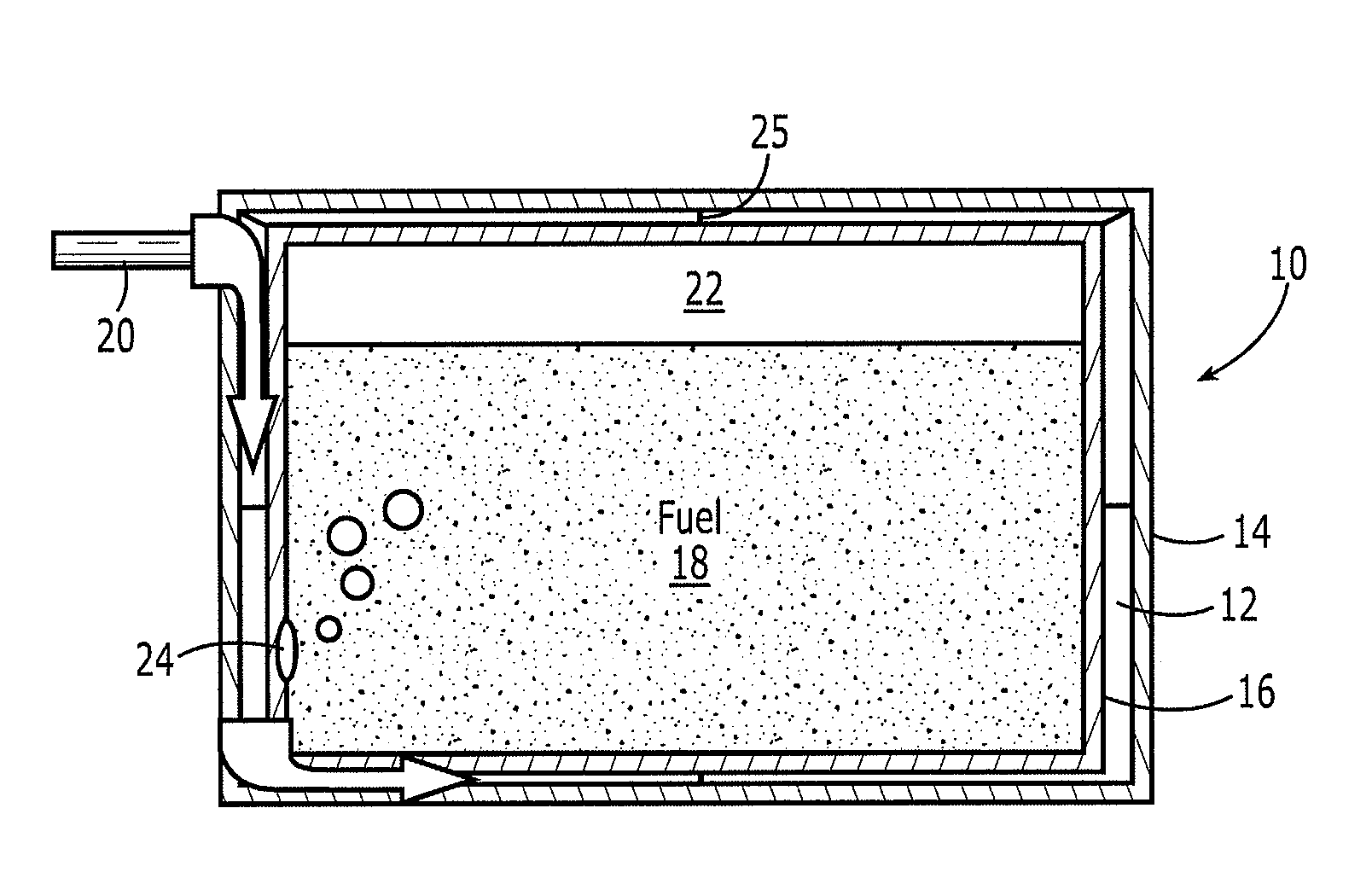
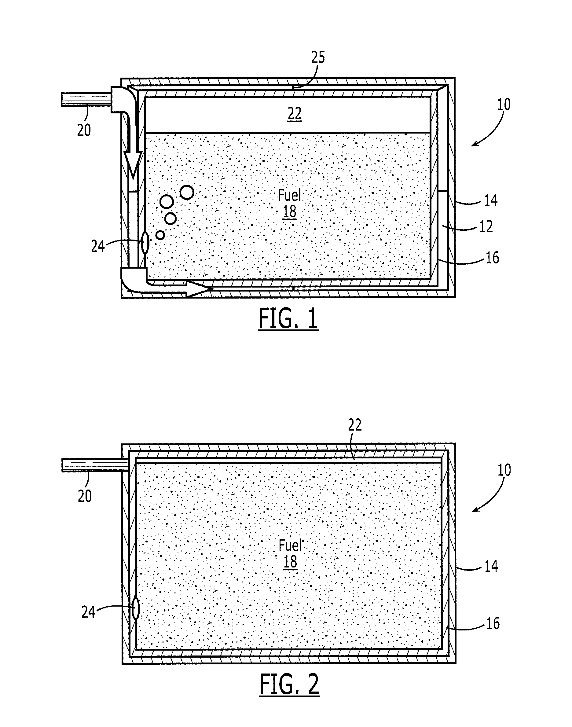
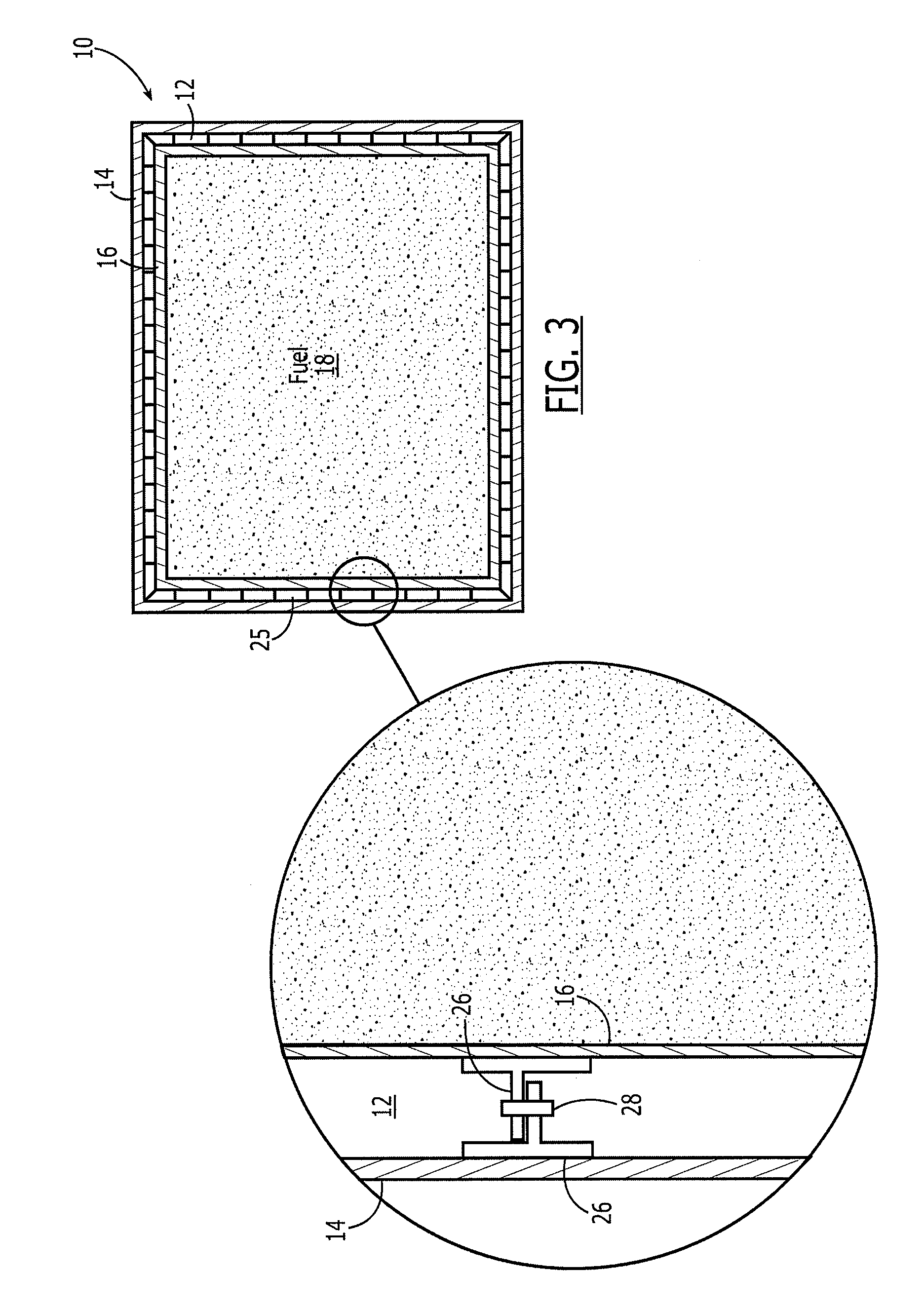
[0023]Referring now to FIG. 1, a side view of a fuel tank assembly 10 according to one embodiment to the present invention is depicted. The fuel tank assembly may be employed in a variety of applications and may be carried, for example, by aircraft or other vehicles. As shown, the fuel tank assembly includes an inflatable bladder 12 defined between an exterior bladder wall 14 and an interior bladder wall 16. The interior bladder wall, in turn, defines a volume for storing fuel 18. In instances in which the fuel...


PUM


Abstract

A fuel tank assembly and associated method are provided which may limit the damage otherwise occasioned by the impact of a ballistic projectile. The fuel tank assembly may include a bladder defined between exterior and interior bladder walls, with the interior bladder wall defining a volume for storing fuel. The exterior bladder wall is at least as or more rigid than the interior bladder wall. The fuel tank assembly can also include connectors between the exterior and interior bladder walls to at least partially limit expansion of the bladder. The fuel tank assembly can also include an inlet opening into the bladder to permit a pressurized gas to be introduced into the bladder. The fuel tank assembly may also include a valve through the interior bladder wall into the volume for storing fuel to permit at least some of the pressurized gas to be introduced therein.

Description

FIELD OF THE INVENTION[0001]Embodiments of the present invention relate generally to fuel tanks and, more particularly, to fuel tanks that can withstand at least some impact from ballistic projectiles.BACKGROUND OF THE INVENTION[0002]Aircraft and other vehicles include fuel tanks for carrying a supply of fuel that may be at least partially consumed during transit. In certain circumstances, a fuel tank carried by an aircraft or other vehicle may be susceptible to being impacted by a ballistic projectile. In a combat or other military situation, for example, a fuel tank of an aircraft or other vehicle may be impacted by gunfire or the like. Alternatively, fragments generated by an uncontained engine failure or the like may also impact the fuel tank of an aircraft or other vehicle and create similar issues.[0003]Regardless of the source of a ballistic projectile, a ballistic projectile can puncture the fuel tank which results not only in damage to the fuel tank, but may also allow fuel...

Claims


Application Information

Patent Timeline
Patent Type & Authority Applications(United States)
IPC IPC(8): F17C1/02B64D37/04F17C13/00
CPCB60K15/03B60K2015/03407B64D2037/325B64D37/32B64D37/06Y10T137/0318Y10T137/0402
Inventor CHILDRESS, JAMES J.DAVIS, II, WARREN A.
Owner THE BOEING CO
Why Eureka
Try Eureka