Print module, information processing device, print system, print unit, ink supply unit, print method, and program
a printing module and information processing device technology, applied in the field of printing modules, can solve the problems of flexibly meeting the needs of users, designing various line printers quickly and inexpensively, and reducing the cost of printing, so as to improve printing efficiency, quick and easy to meet the demands of printing, and increase the effect of siz
- Summary
- Abstract
- Description
- Claims
- Application Information
AI Technical Summary
Benefits of technology
Problems solved by technology
Method used
Image
Examples
first embodiment
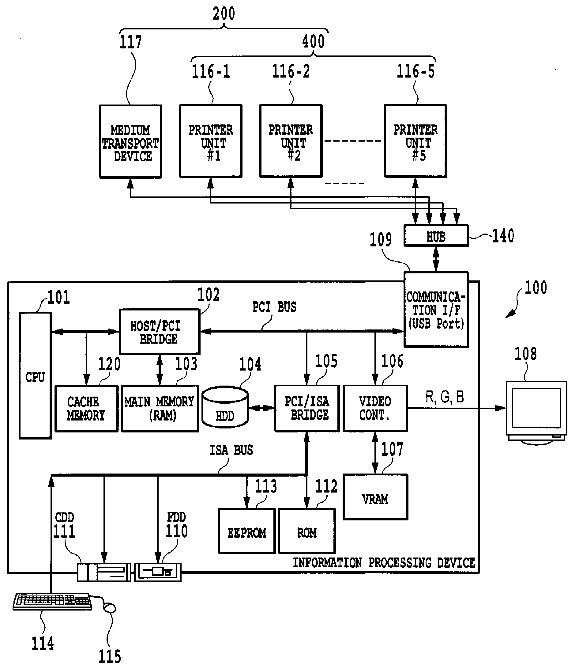
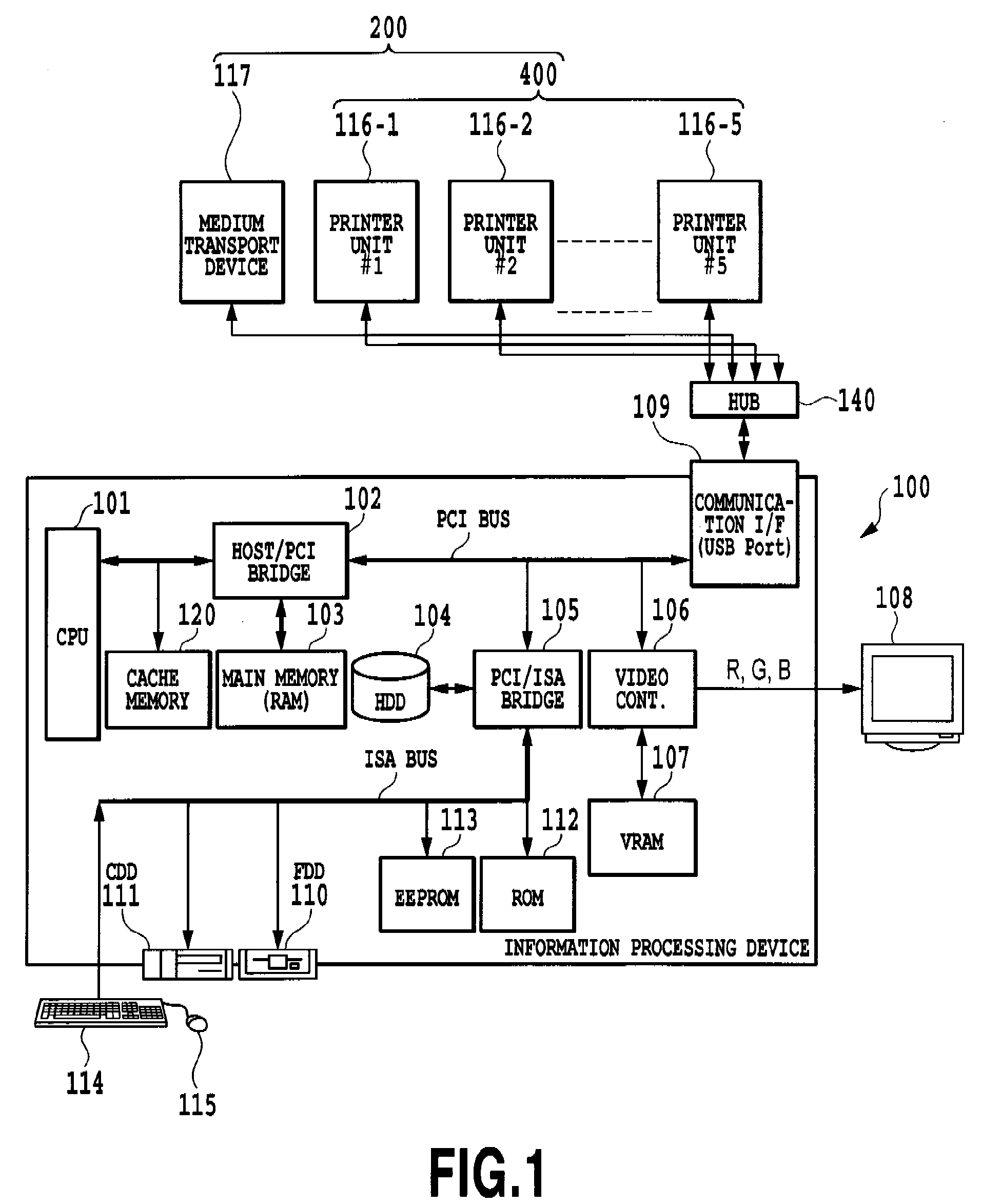
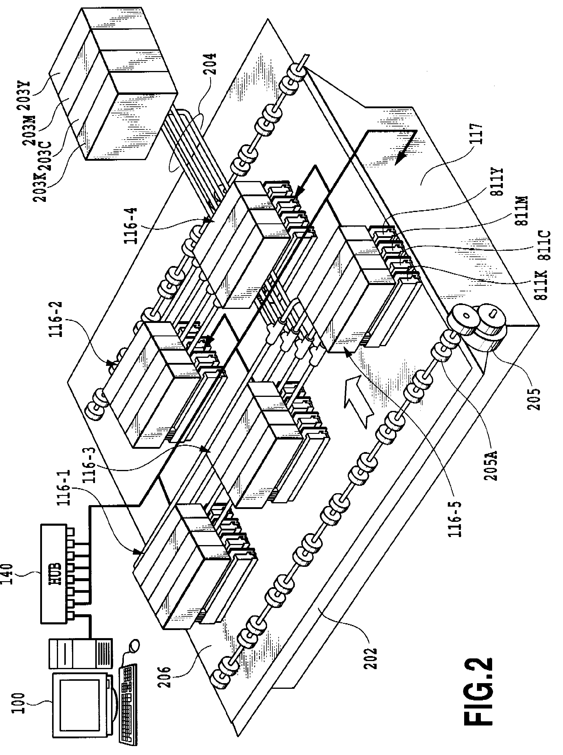
[0121]FIG. 1 and FIG. 2 show an example configuration of an image forming system to which the present invention can be applied.
[0122](Overview of Image Forming System)
[0123]FIG. 1 and FIG. 2 are a block diagram and a schematic perspective view, respectively, showing an outline configuration of an image forming system. A printer composite system of this example comprises an information processing device 100 and an image forming device 200. The image forming device 200 has a medium transport device 117 and a printer composite system400. The printer composite system has a plurality of independent engines or print modules (also referred to as “printing apparatus”, “printers”, or “printing modules”) 116-1 to 116-5.
[0124]The information processing device 100 is a source of data for an image to be formed, and divides one page of image into a plurality of areas and supplies a plurality of divided pieces of image data corresponding to the divided areas to a plurality of print modules 116-1 t...
second embodiment
[0251]FIG. 26 through FIG. 36 shows a second embodiment of this invention, and components identical with those of the preceding embodiment are given like reference numbers and their explanations are omitted.
[0252]This embodiment concerns an example case in which an apparatus of this invention is incorporated in the image forming system of FIG. 1 and FIG. 2. Thus, the outline of the image forming system in this embodiment is similar to that of the preceding embodiment.
[0253](Control System in Print Module)
[0254]FIG. 26 shows an example configuration of the control system in each print module 116. Components similar to those of the preceding embodiment are assigned like reference numbers and their explanations are omitted.
[0255]The pump motor 820 in this example is capable of forward and reverse rotation and drives a pump 548 (see FIG. 27) described later which is built into one end of the ink path of the print head 811 (811Y, 811M, 811C and 811K). The solenoid 821 in this example is ...
third embodiment
[0312]FIG. 37A and FIG. 37B show ink systems of different configurations.
[0313]The ink system of FIG. 37A, as in the first and second embodiment, has a negative pressure application means including a pump P and a valve V in an ink supply path L1 running between an ink tank T and a print head H. The pump P and the valve V correspond to the mechanical pump 36 and the pressure adjust valve 35 in the first embodiment and to the pressure adjust pump 536 and the pressure adjust valve 535 in the second embodiment. The print head H corresponds to the print head 811 in the first and the second embodiment. The ink communication path L1 is equivalent to the ink path for supplying ink from the ink tank to the print head 811 in the first embodiment and to the ink path for supplying ink from the ink tank 540 to the print head 811, i.e., the ink supply path 530 including the circulation path 531 and the connecting path 532, in the second embodiment.
[0314]As described above, FIG. 37A shows a constr...
PUM
 Abstract
Description
Claims
Application Information
 - R&D
- Intellectual Property
- Life Sciences
- Materials
- Tech Scout
- Unparalleled Data Quality
- Higher Quality Content
- 60% Fewer Hallucinations
Browse by: Latest US Patents, China's latest patents, Technical Efficacy Thesaurus, Application Domain, Technology Topic, Popular Technical Reports.
© 2025 PatSnap. All rights reserved.Legal|Privacy policy|Modern Slavery Act Transparency Statement|Sitemap|About US| Contact US: help@patsnap.com


