Power converter and power conversion method
- Summary
- Abstract
- Description
- Claims
- Application Information
AI Technical Summary
Benefits of technology
Problems solved by technology
Method used
Image
Examples
Example
First Example
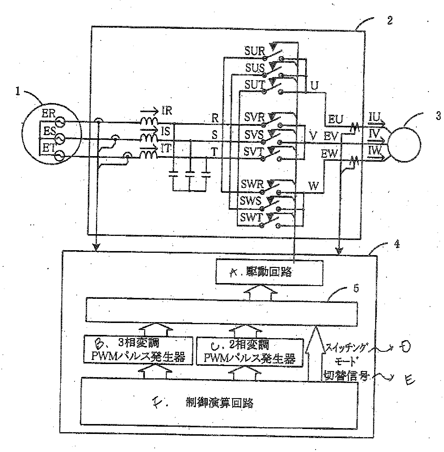
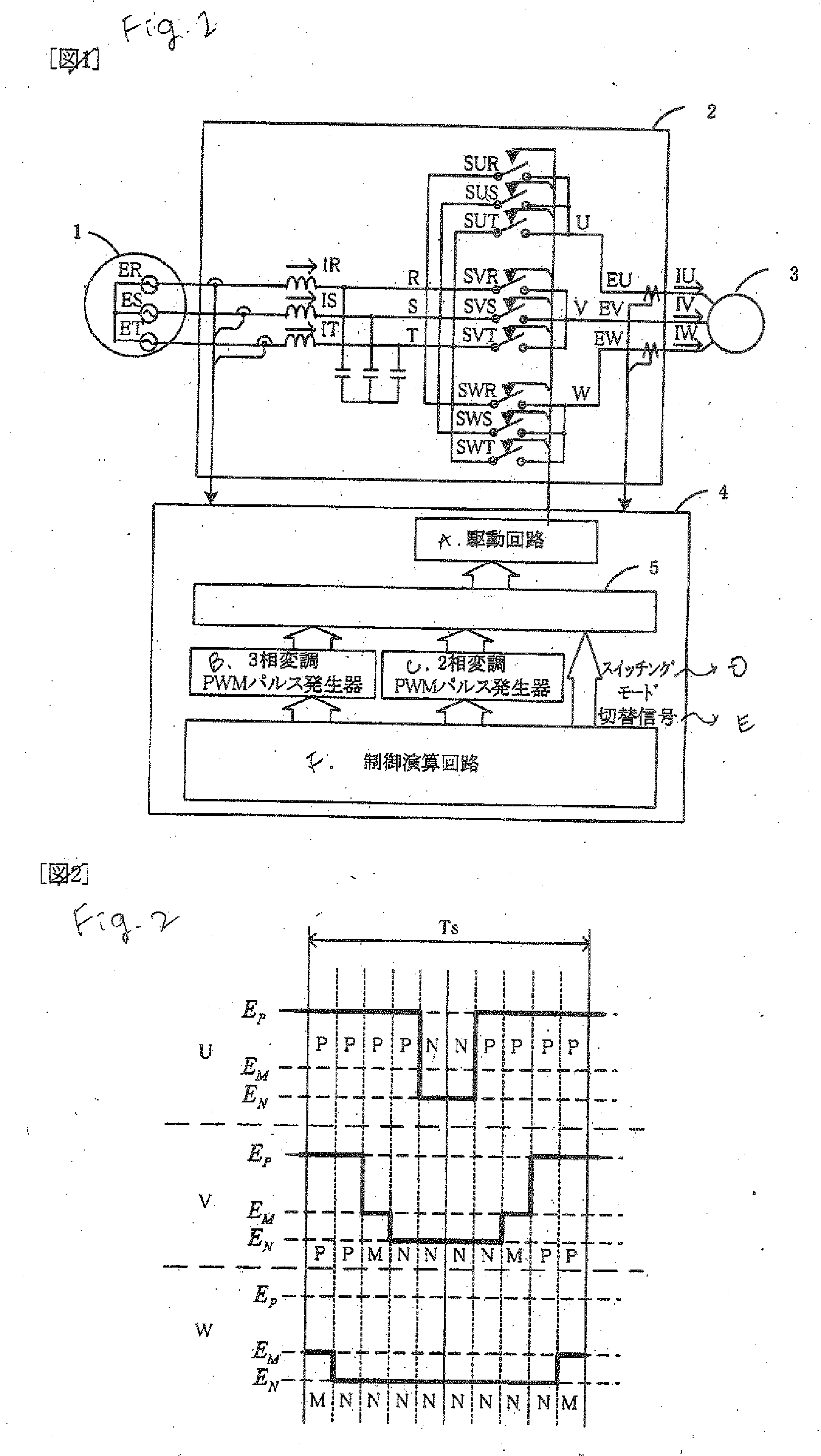
[0099]FIG. 1 is a diagram showing an example of a structure of a power converter according to the present invention. In the drawing, 1 denotes a three-phase power supply, 2 denotes a main circuit of a direct power converter, 3 denotes a load (a motor), and 4 denotes a control circuit of a direct power converting circuit.
[0100]Referring to a three-phase source voltage and a phase, a maximum voltage phase, a minimum voltage phase and an intermediate voltage phase seen from a neutral point are allocated as P, N and M respectively as shown in FIG. 6, and a concept of a space vector is utilized so that an output voltage space vector of a direct power converting circuit can be written as in an example of FIG. 7. In the power converter, usually, a neutral point voltage cannot be directly observed. Therefore, resistances having a value equal to each other are connected like a star in each of phases of a three-phase power supply as sown in FIG. 12, a node voltage is used as a vi...
Example
Second Example
[0105]In the case in which an output voltage command is in the vicinity of an angle formed with an a vector or a b vector, a PWM pulse is narrowed. In a direct power converter, the angles of the a vector and the b vector are not varied. In the case in which the phase of the output voltage command has an angle which is close to the a vector or the b vector, therefore, it is possible to maintain a PWM pulse width without monitoring the PWM pulse width by generating a switching signal to carry out a switching into a three-phase modulation in the control calculating apparatus of FIG. 1. Since a range of the angle to be switched depends on a commutating sequence method and a characteristic of a switching device, it is set corresponding thereto.
Example
Third Example
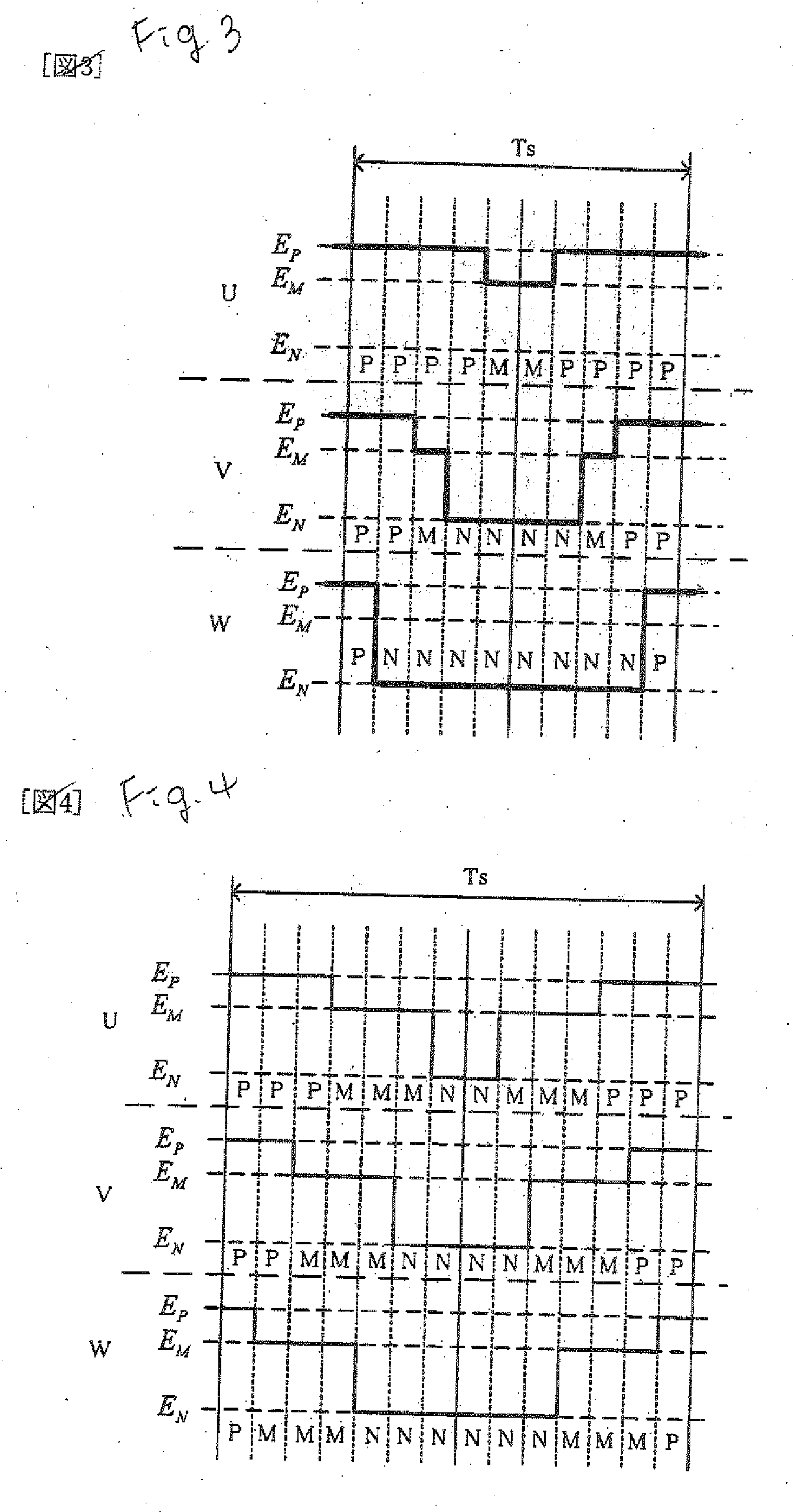
[0106]Also in the case in which there is no problem in that a PWM pulse width is reduced when a switching is carried out depending on a phase of an output voltage command, the switch is performed so that a switching loss is increased. A change in the PWM pulse of FIG. 9 and the PWM pulse of FIG. 10 depends on a voltage state of an input power supply. Therefore, a condition for reducing the PWM pulse width is predicted from the voltage of the input power supply and the phase of the output voltage command. For example, only in the case in which the phase of the output voltage command is close to the angle of the b vector in FIG. 9, it is possible to reduce the switching loss by carrying out a switching from a two-phase modulation into a three-phase modulation. Since the range of the angle to be switched depends on a commutating sequence method and a characteristic of a switching device, it is set corresponding thereto.
PUM
 Abstract
Description
Claims
Application Information
 - R&D
- Intellectual Property
- Life Sciences
- Materials
- Tech Scout
- Unparalleled Data Quality
- Higher Quality Content
- 60% Fewer Hallucinations
Browse by: Latest US Patents, China's latest patents, Technical Efficacy Thesaurus, Application Domain, Technology Topic, Popular Technical Reports.
© 2025 PatSnap. All rights reserved.Legal|Privacy policy|Modern Slavery Act Transparency Statement|Sitemap|About US| Contact US: help@patsnap.com


