Hybrid vehicle drive system

a hybrid vehicle and drive system technology, applied in the direction of electric propulsion mounting, gearboxes, transportation and packaging, etc., can solve the problems of inability to maintain a high degree of efficiency of power transmission from the engine to the drive wheels, and the relationship between the power transmission efficiency of the electric path and the change of the speed ratio of the planetary gear mechanism cannot be significantly changed, so as to achieve the effect of improving fuel economy and high overall power transmission efficiency of the hybrid drive system

Inactive Publication Date: 2009-04-09
TOYOTA JIDOSHA KK
View PDF5 Cites 23 Cited by
  • Summary
  • Abstract
  • Description
  • Claims
  • Application Information

AI Technical Summary

Benefits of technology

[0007]The present invention was made in view of the background art described above. It is therefore an object of this invention to provide a drive system of a hybrid vehicle, which makes it possible to maintain a high degree of overall power transmitting efficiency of the hybrid drive system including the power transmitting efficiency of the electric path, for thereby permitting an improvement of fuel economy of the hybrid vehicle.

Problems solved by technology

In the hybrid vehicle drive system in question, however, the connections of the engine, first electric motor and drive wheels to the rotary elements of the planetary gear mechanism in the form of the carrier, sun gear and ring gear cannot be changed, so that the relationship between the power transmitting efficiency of the electric path and the change of the speed ratio of the planetary gear mechanism cannot be changed considerably, whereby it is not possible to maintain a high degree of efficiency of power transmission from the engine to the drive wheels, over a wide range of change of the speed ratio of the planetary gear mechanism.

Method used


Image

  • Hybrid vehicle drive system
  • Hybrid vehicle drive system
  • Hybrid vehicle drive system

Examples


first embodiment

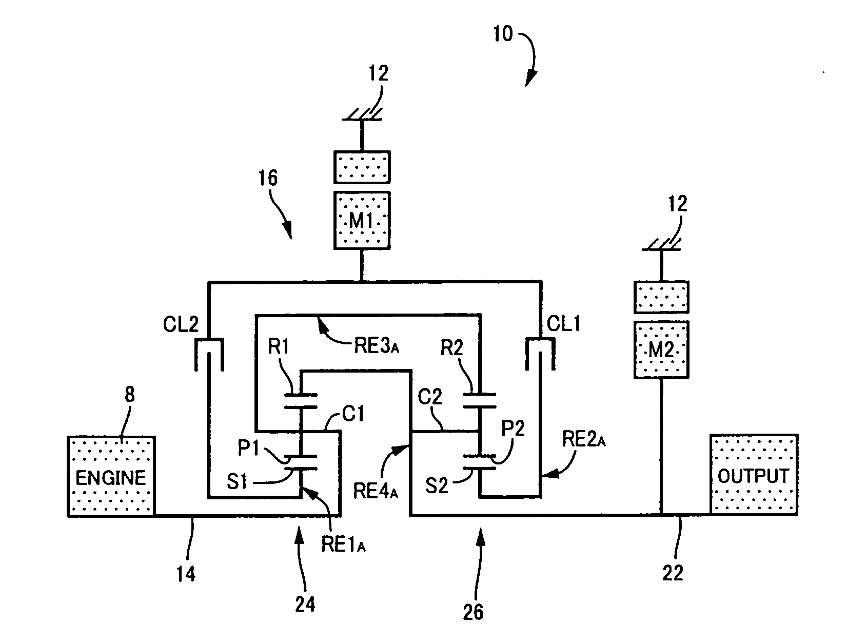
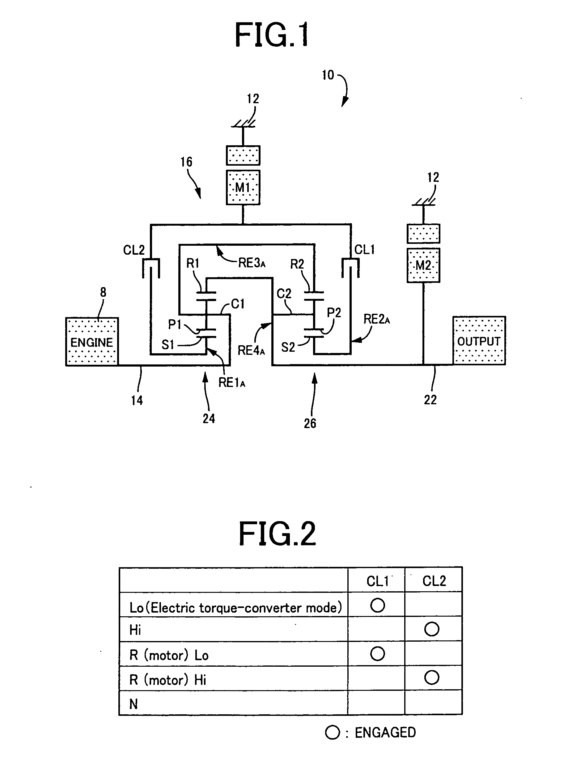
[0054]Referring to the schematic view of FIG. 1, there is shown a drive system 10 of a hybrid vehicle, which is constructed according to the first embodiment of the present invention. As shown in FIG. 1, the drive system 10 includes: an engine 8; an input rotary member in the form of an input shaft 14 connected to the engine 8 either directly or indirectly via a pulsation absorbing damper (vibration damping device) not shown, to receive an output of the engine 8; a differential mechanism in the form of a power distributing mechanism 16 connected to the input shaft 14; and an output rotary member in the form of an output shaft 22 connected to the power distributing mechanism 16. The input shaft 12, power distributing mechanism 16 and output shaft 22 are coaxially disposed on a common axis within a stationary member in the form of a transmission casing 12 (hereinafter referred to as “casing 12”) attached to a body of the hybrid vehicle, and are connected in series with each other. The...

second embodiment

[0103]The schematic view of FIG. 11 shows an arrangement of a drive system 110 constructed according to the second embodiment of the invention. This drive system 110 is different from the drive system 10 only in that a power distributing mechanism 116 is provided in the drive system 110, in place of the power distributing mechanism 16 provided in the drive system 10.

[0104]As shown in FIG. 11, the drive system 110 includes the engine 8, input shaft 14 connected to the engine 8, a differential mechanism in the form of the above-indicated power distributing mechanism 116, and output shaft 22 connected to the power distributing mechanism 116. The engine 8, input shaft 14, power distributing mechanism 116 and output shaft 22 are coaxially disposed on the common axis within the stationary member in the form of the casing 12 attached to the body of the hybrid vehicle, and are connected in series with each other, as in the drive system 10 of the first embodiment shown in FIGS. 1 and 7. Like...

third embodiment

[0121]In the drive systems 10, 110 according to the first and second embodiments, the power transmitting path between the engine 8 and the drive wheels 38 is provided with the power distributing mechanism 16, 116. However, a drive system according to the principle of this invention may be provided with a first transmission in the form of the power distributing mechanism 16, 116, and a second transmission 160 which is disposed in a power transmitting path between the engine 8 or drive wheels and the power distributing mechanism 16, 116 and the speed ratio of which is variable. FIG. 15 shows an example of such a drive system in the form of the drive system 10 of the first embodiment as modified according to the third embodiment, such that the drive system 10 is modified to be provided with the second transmission 160 disposed between the power distributing mechanism 16 and the drive wheels 38. The drive system 10 according to the third embodiment has power transmitting efficiency η hi...


PUM


Abstract

A drive system of a hybrid vehicle, including an engine, a first electric motor, a second electric motor operatively connected to a drive wheel of the hybrid vehicle, and two planetary gear mechanisms, and wherein the two planetary gear mechanisms have at least four rotary elements arranged to permit the drive system to be placed in a selected one of a first operation mode in which the rotary element connected to the engine and the rotary element connected to the first electric motor are disposed on opposite sides of the rotary element connected to the drive wheel and the second electric motor, as seen in a collinear chart in which the four rotary elements are located at respective four different positions along a base line, and a second operation mode in which the rotary element connected to the first electric motor and the rotary element connected to the drive wheel and the second electric motor are disposed on opposite sides of the rotary element connected to the engine, as seen in said collinear chart.

Description

[0001]The present application claims priority from Japanese Patent Application No. 2007-262926 filed on Oct. 9, 2007, the disclosure of which is herein incorporated by reference in its entirety.BACKGROUND OF THE INVENTION[0002]1. Field of the Invention[0003]The present invention relates in general to a drive system of a hybrid vehicle, and more particularly to techniques for improving fuel economy of a hybrid vehicle drive system[0004]2. Discussion of Prior Art[0005]JP-2000-197208A discloses a drive system of a hybrid vehicle, which includes an engine, a first electric motor, a second electric motor, and a planetary gear mechanism having three rotary elements. The planetary gear mechanism has a first rotary element in the form of a carrier connected to the engine, a second rotary element in the form of a sun gear connected to the first electric motor, and a third rotary element in the form of a ring ear connected to the second electric motor and drive wheels of the hybrid vehicle. A...

Claims


Application Information

Patent Timeline
Patent Type & Authority Applications(United States)
IPC IPC(8): F16H3/72B60K6/365B60K6/40B60K6/445B60K6/547B60K17/04B60L15/20B60L50/16B60W10/06B60W10/08B60W10/10B60W20/00F16H3/66
CPCB60K1/02B60K6/365B60K6/40B60K6/445F16H3/725Y02T10/6239F16H2037/0866F16H2037/0873F16H2200/2007F16H2200/2035Y02T10/7258F16H3/728Y02T10/62Y02T10/72
Inventor KUMAZAKI, KENTAMATSUBARA, TOORUTABATA, ATSUSHIIMAI, KEITAKAIFUKU, MASAKAZUYOSHIDA, MASAKIIMAMURA, TATSUYAIWASE, YUJI
Owner TOYOTA JIDOSHA KK
Why Eureka
Try Eureka