
Semi-automated ophthalmic photocoagulation method and apparatus

a semi-automated, ophthalmic technology, applied in the field of ophthalmic treatment of patients eyes, can solve the problems of requiring great physician skill, and requiring a large amount of tim

Active Publication Date: 2009-04-09
IRIDEX CORP
View PDF25 Cites 109 Cited by
  • Summary
  • Abstract
  • Description
  • Claims
  • Application Information

AI Technical Summary

Benefits of technology

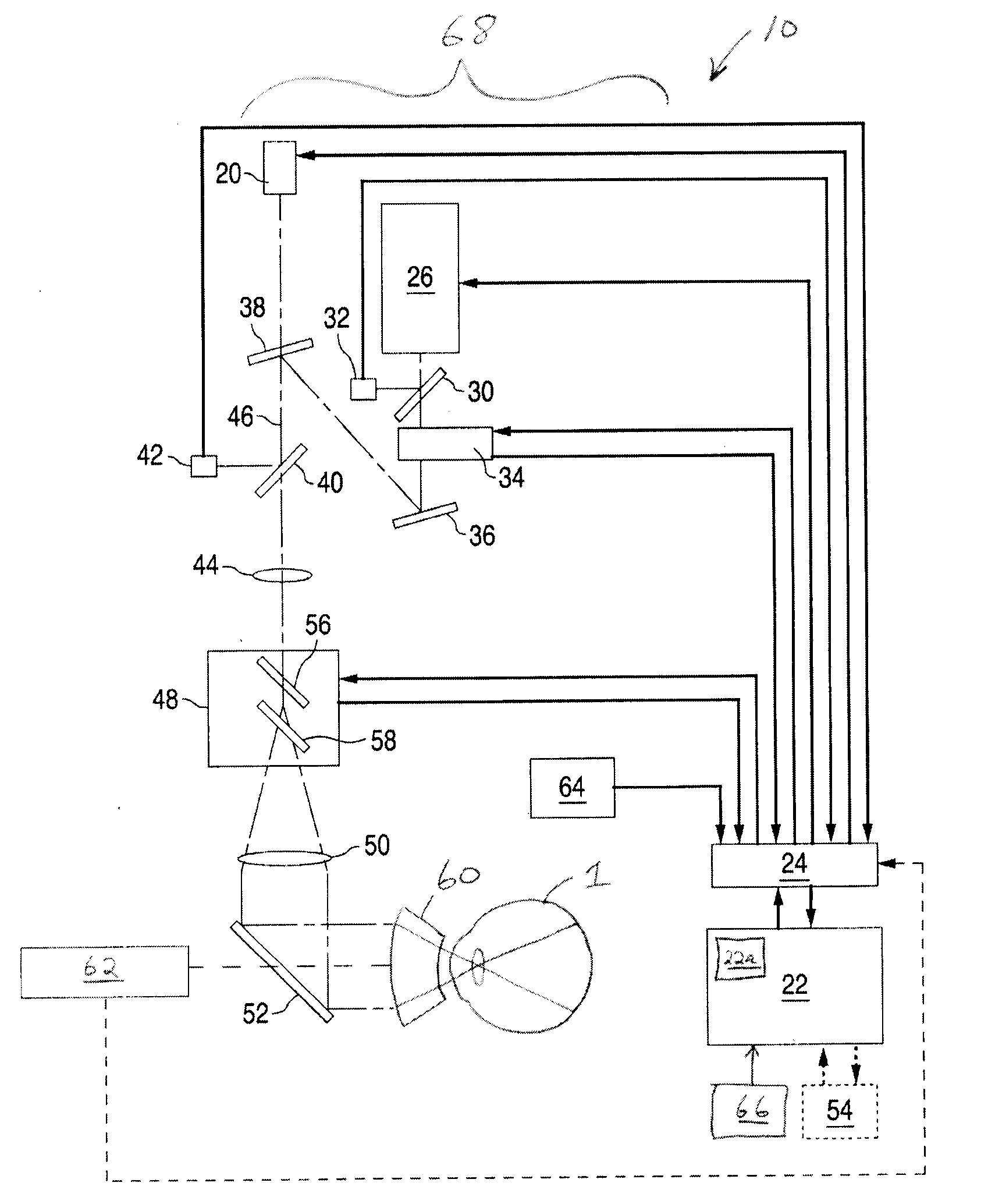
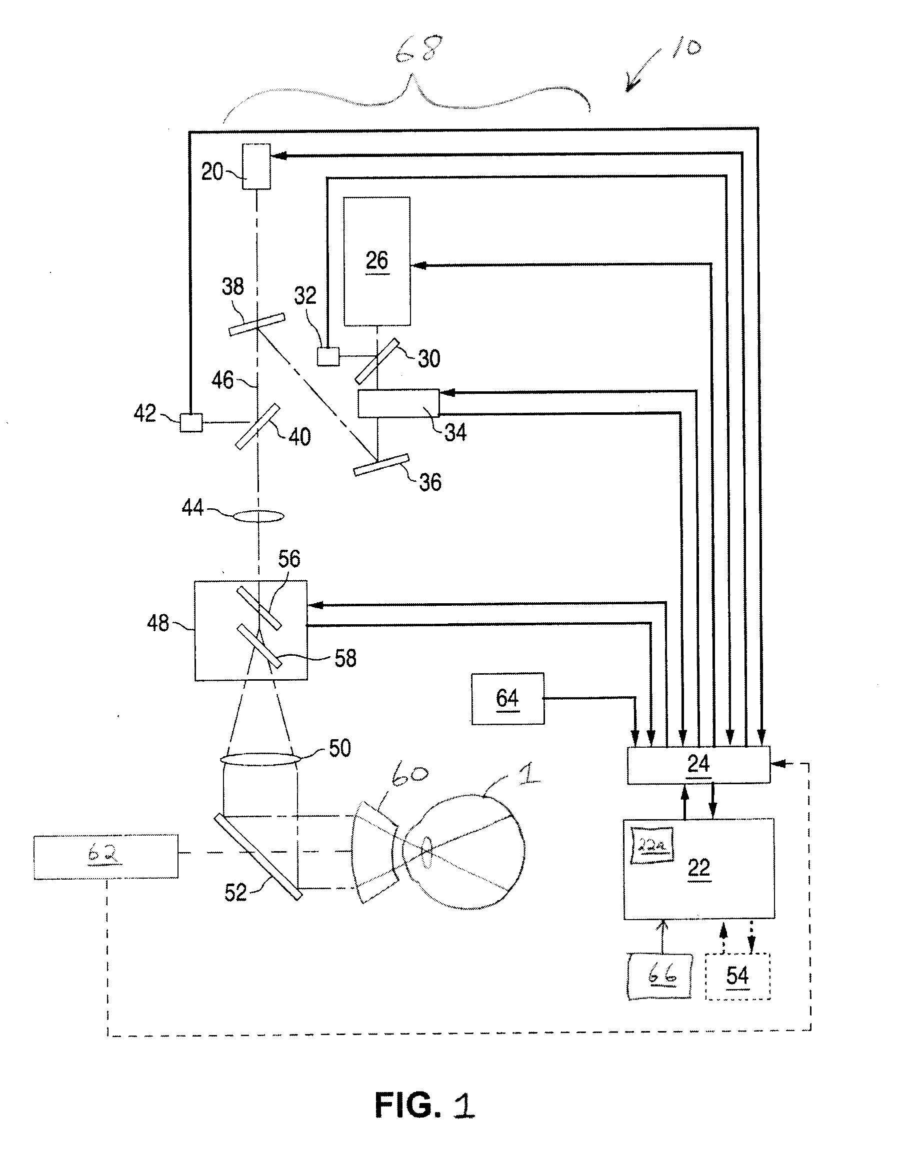
[0006]The present invention solves the aforementioned problems by providing an ophthalmic treatment system for performing therapy on target tissue in a patient's eye that includes a light source for producing treatment light, a delivery system for delivering the treatment light to the patient's eye, a camera for capturing a live image of the patient's eye, and control electronics for controlling the delivery system, for registering a pre-treatment image of the patient's eye to the live image captured by the camera, wherein the pre-treatment image includes a treatment template that identifies target tissue within the patient's eye, and for verifying whether or not the delivery system is aligned to the target tissue defined by the treatment template. A trigger device is connected to the control electronics, wherein in response to both an activation of the trigger device and the verification that the delivery system is aligned to the target tissue, the control electronics are configured to control the delivery system to project the treatment light onto the patient's eye.

Problems solved by technology

While this type of visible laser light treatment may halt the progress of the underlying disease, it can be problematic.
One problem is that some ophthalmic treatments require the application of a large number of laser doses to the retina, which can be tedious and time consuming.
Since some treatments can require hundreds of laser beam spots to treat the target tissues, the overall treatment time can be quite long and require great physician skill to ensure a precise and adequate treatment of the entire target tissue area is accomplished.
However, rapid delivery of multiple beam spots in patterns raises new issues.
For example, the exposure time is limited because of possible eye movement, and even with short exposure times there can be patient eye movement at the moment the physician triggers the application of the treatment pattern that could result in the application of the treatment pattern to non-targeted tissue.
Present systems and techniques for applying patterns of spots have no capability of ensuring the tissue targeted for treatment by the physician is the same as that identified in the pre-treatment images.
Rapid eye movements called saccades cannot be adequately tracked or compensated for by physicians.
Anesthetizing eye muscles using an injection of an anesthetic agent behind the eye can stabilize the eye but carries a risk of perforating the eye, the optic nerve or the blood vessels, is quite painful, and could even cause death.

Method used


Image

  • Semi-automated ophthalmic photocoagulation method and apparatus
  • Semi-automated ophthalmic photocoagulation method and apparatus
  • Semi-automated ophthalmic photocoagulation method and apparatus

Examples


Embodiment Construction

[0015]A system and method for semi-automated, doctor-in-the-loop, ophthalmic treatment of target eye tissue is disclosed which accurately identifies tissue areas for treatment, aligns a light delivery system to those tissue areas for treatment, and adjusts alignment to compensate for patient eye movement during treatment.

Pattern Generation System

[0016]FIG. 1 is a schematic diagram of a system 10 suitable for performing semi-automated ophthalmic treatment of a patient's eye tissue. Alignment light (for an aiming beam or alignment pattern) is created using an alignment light source 20, which may be controlled by control electronics 22 via an input / output device 24. It should be noted that the use of alignment light is optional, and therefore elements for its generation and use could be omitted. Therapeutic light is created using a therapeutic light source 26. Light sources 20 and 26 can be any gas or solid state laser device, or even one or more light emitting diodes. Light sources 20...


PUM


Abstract

An ophthalmic treatment system and method for performing therapy on target tissue in a patient's eye. A delivery system delivers treatment light to the patient's eye and a camera captures a live image of the patient's eye. Control electronics control the delivery system, register a pre-treatment image of the patient's eye to the camera's live image (where the pre-treatment image includes a treatment template that identifies target tissue within the patient's eye), and verify whether or not the delivery system is aligned to the target tissue defined by the treatment template. The control electronics control the delivery system to project the treatment light onto the patient's eye in response to both an activation of a trigger device and the verification that the delivery system is aligned to the target tissue, as well as adjust delivery system alignment to track eye movement.

Description

FIELD OF THE INVENTION[0001]The present invention pertains generally to the ophthalmic treatment of a patient's eye, and more particularly to a machine and method for semi-automated ophthalmic photomedical treatment of a patient's eye.BACKGROUND OF THE INVENTION[0002]Presently, conditions such as diabetic retinopathy, vein occlusion and age-related macular degeneration have been treated with photocoagulation induced by visible laser light. While this type of visible laser light treatment may halt the progress of the underlying disease, it can be problematic.[0003]One problem is that some ophthalmic treatments require the application of a large number of laser doses to the retina, which can be tedious and time consuming. Such treatments call for the application of each dose in the form of a laser beam spot applied to the target tissue for a predetermined amount of time. The physician is responsible for ensuring that each laser beam spot is properly positioned on the intended target t...

Claims


Application Information

Patent Timeline
Patent Type & Authority Applications(United States)
IPC IPC(8): A61F9/007
CPCA61F9/0079A61F9/008A61F9/00821A61F9/00823A61F2009/00863A61F2009/00878A61F2009/00897A61F2009/00846A61B3/102A61B3/135A61F2009/00851
Inventor CHARLES, STEVEN THOMAS
Owner IRIDEX CORP
Learn More