Fuel injection control system with exempt area of fuel map

a technology of fuel map and control system, which is applied in the direction of electrical control, process and machine control, etc., can solve the problems of increasing vehicle emissions and exceeding acceptable levels, and achieve the effect of increasing vehicle emissions and increasing vehicle emissions

Inactive Publication Date: 2009-04-09
DYNOJET RES
View PDF4 Cites 12 Cited by
  • Summary
  • Abstract
  • Description
  • Claims
  • Application Information

AI Technical Summary

Benefits of technology

[0006]Changing vehicle performance with a fuel management system may increase vehicle emissions. Some states, notably California, have air quality r...

Problems solved by technology

Changing vehicle performance with a fuel management system may increase vehicle emissions.
Some states, notably California, have air quality regul...

Method used


Image

  • Fuel injection control system with exempt area of fuel map
  • Fuel injection control system with exempt area of fuel map
  • Fuel injection control system with exempt area of fuel map

Examples


Embodiment Construction

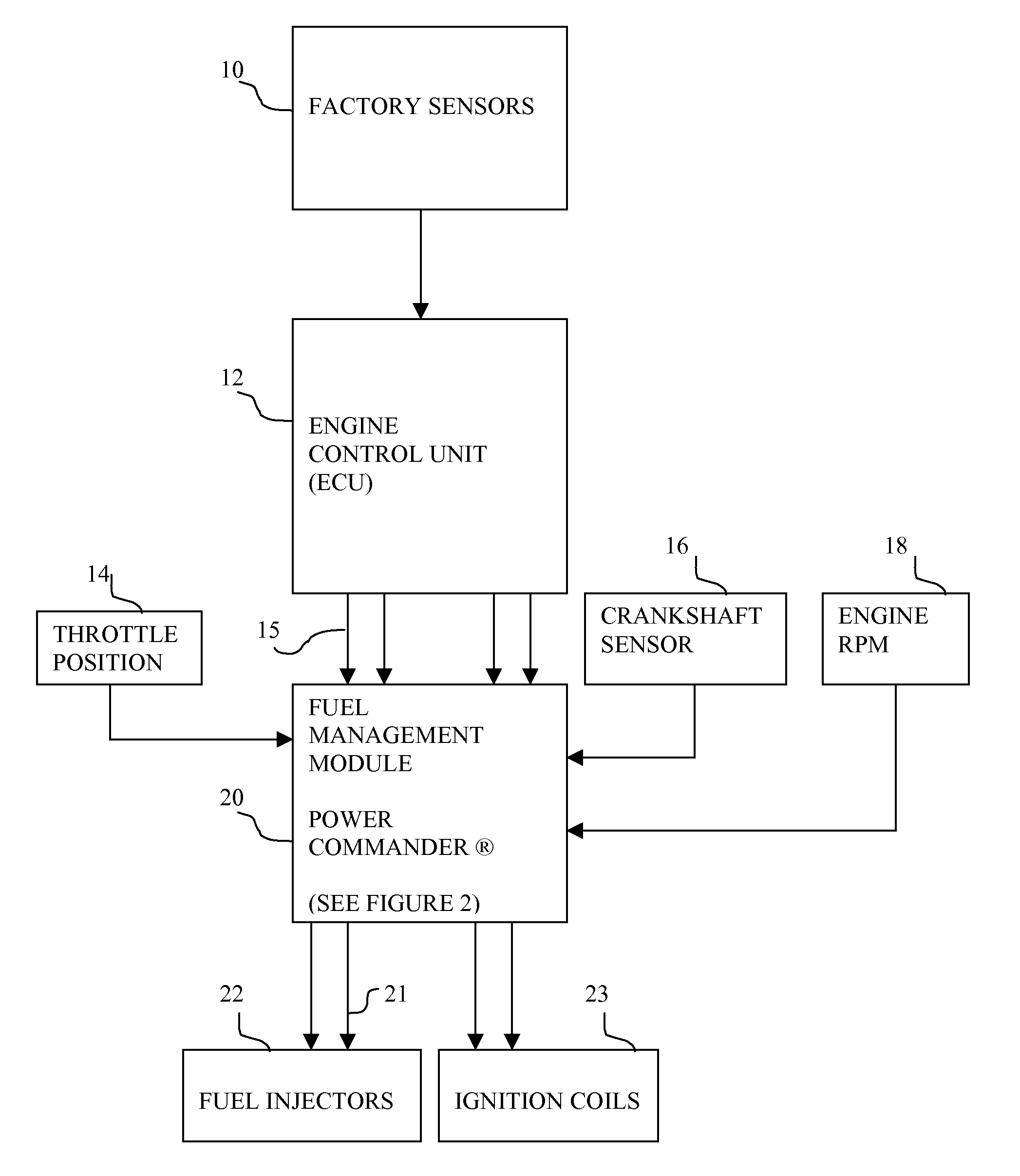
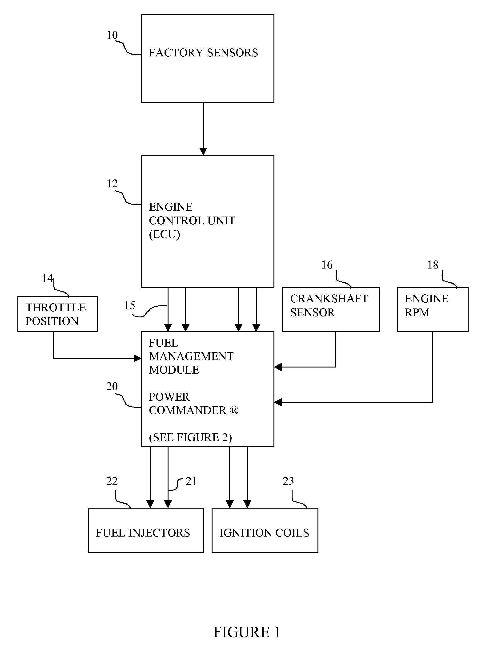
[0023]As shown in the block diagram of FIG. 1, a fuel-injected engine includes factory sensors 10, an engine control unit (ECU) 12, fuel injector drivers 22 and ignition coil drivers 23. A fuel management module 20 is positioned between the ECU 12 and the fuel injector drivers 22. In some models where the fuel management module alters engine timing, the fuel management module 20 is also positioned between the output of the ECU 12 and the ignition coil drivers 23.

[0024]Specifically, the fuel management module 20 is coupled to some of the engine sensors, namely the throttle position sensor 14, the engine RPM sensor 18 and crankshaft angle sensor 16. The ECU fuel injector control signals 15 are input to the fuel management module 20. The fuel management module 20 provides offset fuel injector control signals 21 to the fuel injectors 22. By positioning the fuel management module 20 between the ECU 12 and the fuel injectors 22 (and as well as the ignition coils 23), the fuel management m...


PUM


Abstract

A fuel management system for fuel injected vehicles permits a user to modify vehicle performance without exceeding acceptable standards for vehicle emissions. A portion of the fuel management system fuel map is designated as an exempt area in which the user is not permitted to modify the fuel offset values.

Description

FIELD OF INVENTION[0001]The present invention relates to the field of fuel management systems for fuel-injected internal combustion engines.BACKGROUND OF THE INVENTION[0002]In a fuel-injected internal combustion engine, an electronic control unit (ECU) turns on the fuel injectors at the appropriate time to inject fuel into the cylinders. The percentage of time a fuel injector is open during the fuel cycle is known as the fuel injector duty cycle. Input data to the vehicle ECU, i.e., engine RPM, throttle position, crankshaft position and the like, are provided by factory installed engine sensors. The vehicle manufacturer provides stock ECU programming defining the fuel injector duty cycle for each value of throttle position and engine speed, which determines the fuel economy, power and emission levels for the vehicle.[0003]Aftermarket fuel management systems that modify the performance of fuel-injected engines in cars and motorcycles are known. The Power Commander® fuel injection con...

Claims


Application Information

Patent Timeline
IPC IPC(8): F02D41/30
CPCF02D41/2422H04L12/66F02D41/2467F02D41/2448
Inventor DRAZICH, TYLER T
Owner DYNOJET RES
Why Eureka
Try Eureka