Check patentability & draft patents in minutes with Patsnap Eureka AI!

Capacitive detector

Inactive Publication Date: 2009-04-16
FREESCALE SEMICON INC
View PDF10 Cites 9 Cited by
  • Summary
  • Abstract
  • Description
  • Claims
  • Application Information

AI Technical Summary

Benefits of technology

[0024]Other aspects and advantages of the present invention will become apparent from the following description, taken in conjunction with the accompanying drawings, illustrating by way of example the principles of the invention.

Problems solved by technology

However, when using a product, the application and measurement of acceleration is not practical from the aspects of cost and complicatedness.

Method used


Image

  • Capacitive detector
  • Capacitive detector
  • Capacitive detector

Examples


Embodiment Construction

[0018]The present invention provides a capacitive detector that accurately detects a physical quantity with a simple circuitry.

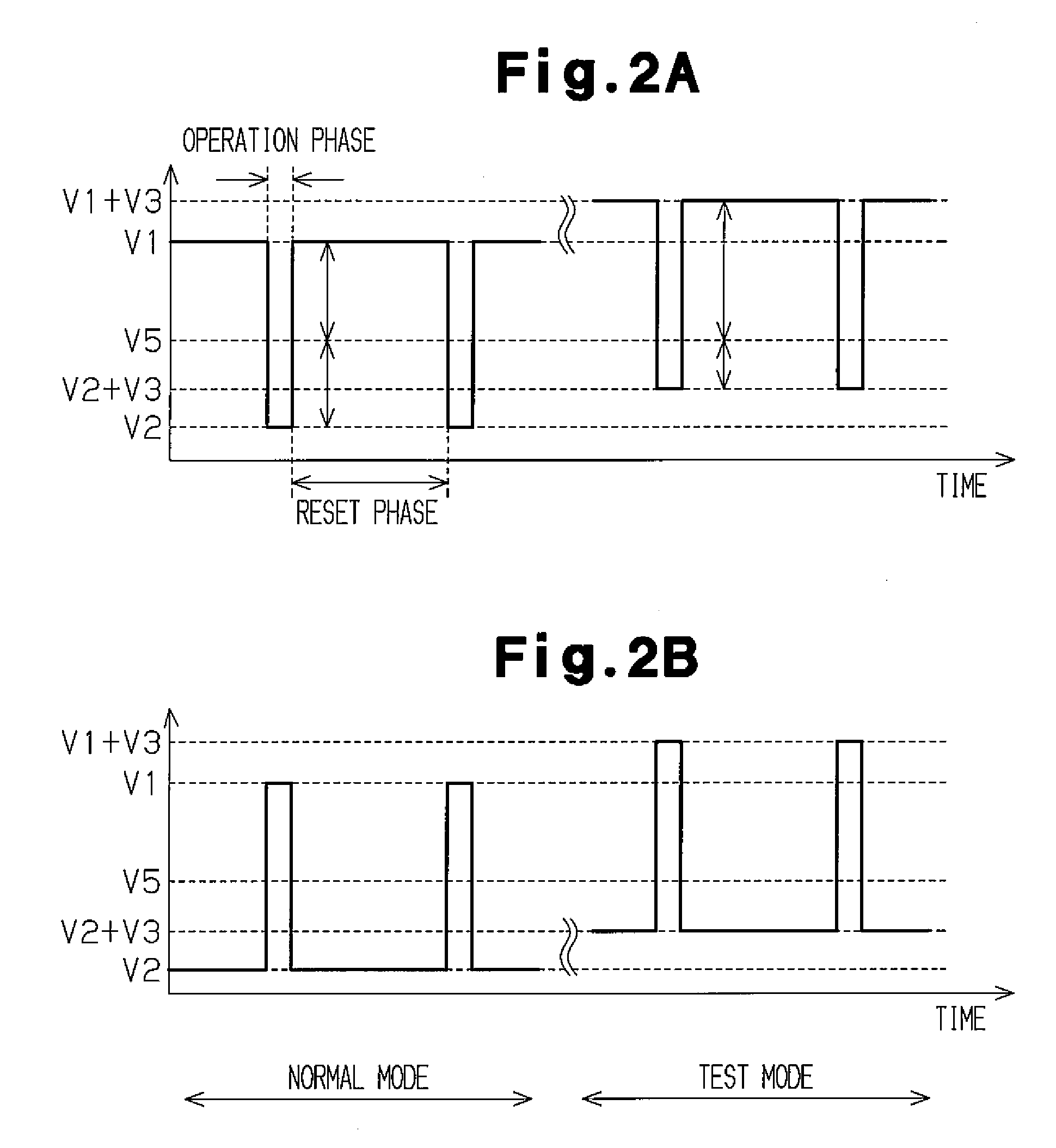
[0019]One aspect of the present invention is a capacitive detector for measuring a physical quantity. The capacitive detector includes a movable electrode which moves in accordance with a change in a physical quantity. A first fixed electrode and second fixed electrode are arranged facing toward the movable electrode. A signal controller applies voltages in a cycle including a first phase and a second phase. The signal controller applies a first voltage to the first fixed electrode and a second voltage to the second fixed electrode during the first phase and applies the second voltage to the first fixed electrode and the first voltage to the second fixed electrode during the second phase. A capacitance converter outputs voltage corresponding to a change in capacitance calculated from a measurement of an amount of change in charge accumulated in the movable e...


PUM


Abstract

A capacitive detector that accurately detects a physical quantity with a simple circuitry. An acceleration sensor includes a capacitance converter, an amplifier, a detection element unit, and a signal controller. The capacitor converter, which includes an operational amplifier, a switch, and a capacitor, converts a change in differential capacitance, which is obtained by fixed electrodes and a movable electrode, to voltage. The operational amplifier has a non-inversion input terminal, which receives a reference voltage. The signal controller supplies voltage that is applied to the fixed electrodes of the detection element unit. The signal controller includes a bias supply unit, which applies a predetermined bias voltage to the fixed electrodes during a test mode.

Description

BACKGROUND OF THE INVENTION[0001]The present invention relates to a capacitive detector for detecting a physical quantity, such as acceleration, angular velocity, and pressure.[0002]Capacitive detectors are used in acceleration sensors, angular velocity sensors, pressure sensors, and the like. Detectors having microscopic structures have been realized by implementing microelectromechanical systems (MEMS) technology. In such a capacitive detector, a movable electrode and fixed electrode are arranged facing toward each other to detect a physical quantity based on the capacitance between the movable and fixed electrodes. FIG. 4 shows the structure of a prior art acceleration sensor CS1. The acceleration sensor CS1 includes a detection element unit 10, a capacitance converter 20, a signal controller 30, and an amplifier 40.[0003]The detection element unit includes fixed electrodes 11 and 12 and a movable electrode 13, which has a beam structure and faces toward the fixed electrodes 11 a...

Claims


Application Information

Patent Timeline
IPC IPC(8): G01P15/125
CPCG01D5/24G01P21/00G01P15/125G01D5/2417
Inventor SASAKI, HIROAKISHIKATA, EIJI
Owner FREESCALE SEMICON INC
Features
  • R&D
  • Intellectual Property
  • Life Sciences
  • Materials
  • Tech Scout
  • Unparalleled Data Quality
  • Higher Quality Content
  • 60% Fewer Hallucinations
Learn More