Physiological parameter detector

a technology of physiological parameters and detectors, applied in the field of physiological sensors, can solve problems such as electromagnetic noise, and achieve the effects of improving and increasing the electromagnetic noise immunity of the sensor

Inactive Publication Date: 2009-04-16
JPMORGAN CHASE BANK NA
View PDF5 Cites 202 Cited by
  • Summary
  • Abstract
  • Description
  • Claims
  • Application Information

AI Technical Summary

Benefits of technology

[0006]Aspects of the present disclosure include a detector providing protection against electromagnetic interference for an included sensor. In an embodiment, the detector includes a sensor, a carrier, and a shield. The shield and carrier are coupled to act as a Faraday cage, improving the electromagnetic noise immunity of the sensor.
[0007]In an embodiment, the carrier can be formed using a ceramic material. The carrier can include a cavity for placement of a sensor. The carrier and sensor are at least partially covered by shielding material in order to increase electromagnetic noise immunity of the sensor.
[0008]In an embodiment, shielding material can be printed directly on the sensor. The shielding material can partially cover one side or multiple sides of the sensor. The shielding material can be electrically coupled to ground or left floating to increase electromagnetic noise immunity of the sensor.
[0009]Aspects of the present disclosure also include methods f

Problems solved by technology

Physiological monitoring systems are often operated in e

Method used


Image

  • Physiological parameter detector
  • Physiological parameter detector
  • Physiological parameter detector

Examples


Embodiment Construction

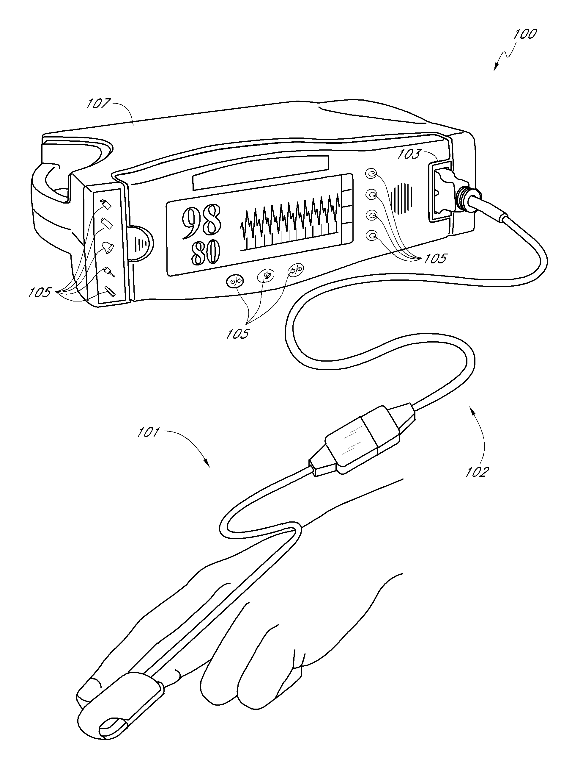
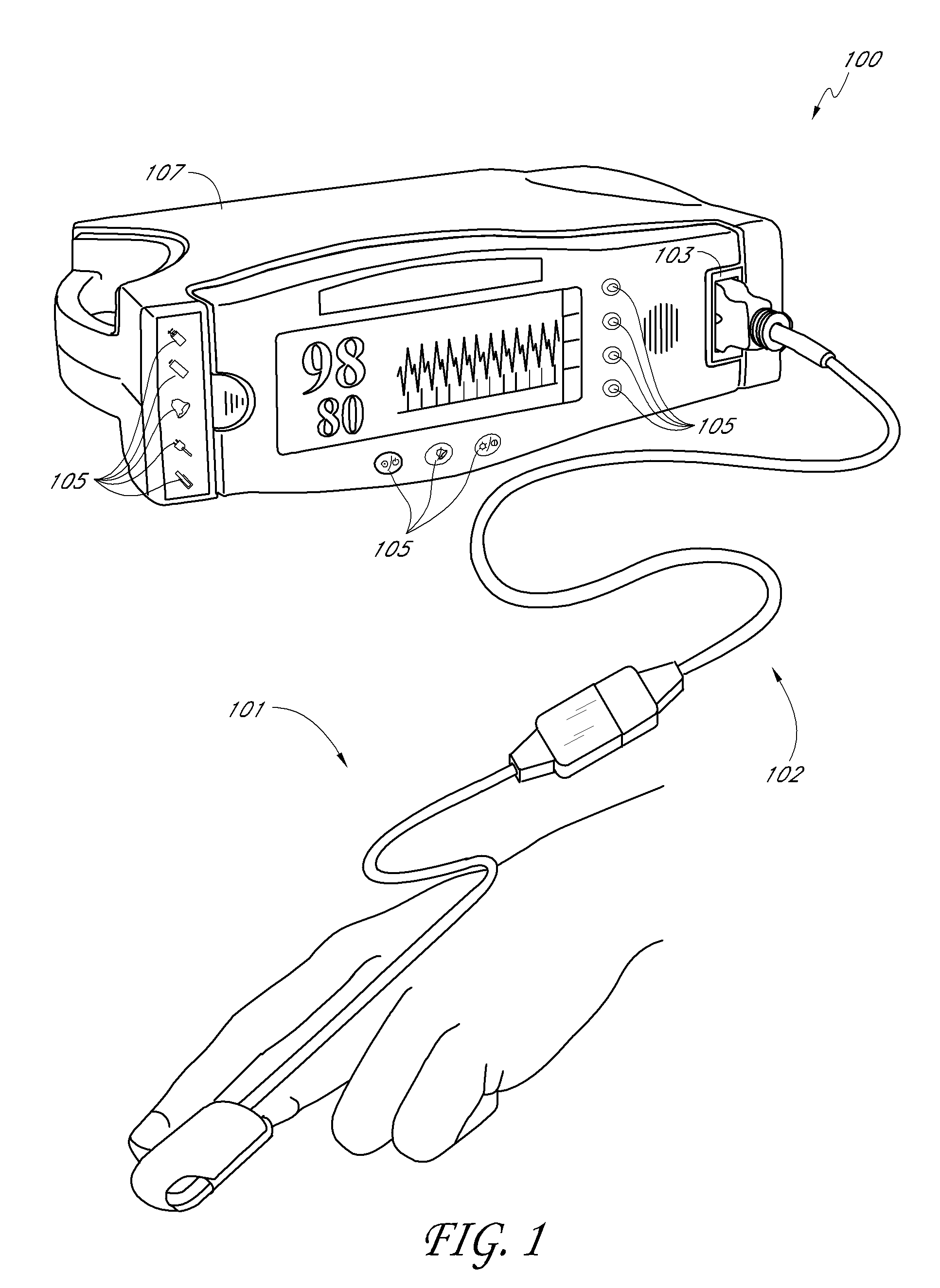
[0031]FIG. 1 illustrates an embodiment of a physiological measurement system 100 having a monitor 107 and a sensor assembly 101. The physiological measurement system 100 allows the monitoring of a person, including a patient. In particular, the multiple wavelength sensor assembly 101 allows the measurement of blood constituents and related parameters, including, for example, oxygen saturation, HbCO, HBMet and pulse rate, among others.

[0032]In an embodiment, the sensor assembly 101 is configured to plug into a monitor sensor port 103. Monitor keys 105 provide control over operating modes and alarms, to name a few. A display 107 provides readouts of measured parameters, such as oxygen saturation, pulse rate, HbCO and HbMet to name a few.

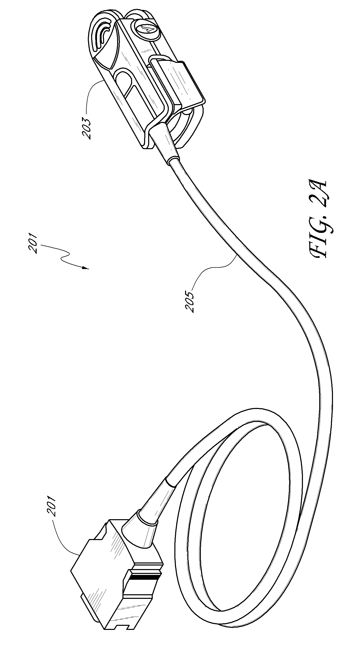
[0033]FIG. 2A illustrates a multiple wavelength sensor assembly 201 having a sensor 203 adapted to attach to a tissue site, a sensor cable 205 and a monitor connector 201. In an embodiment, the sensor 203 is incorporated into a reusable finger clip ada...


PUM


Abstract

A pulse oximetry sensor has an emitter adapted to transmit optical radiation into a tissue site and a ceramic detector adapted to receive optical radiation from the emitter after tissue site absorption. The detector is surrounded by shielding material to reduce undesirable electromagnetic interference.

Description

REFERENCE TO RELATED APPLICATION[0001]The present application claims priority benefit under 35 U.S.C. §119 (e) from U.S. Provisional Application No. 60 / 979,658, filed Oct. 12, 2007, entitled “Ceramic Detector,” which is incorporated herein by reference. RELATED CASES[0002]The present disclosure is generally related to U.S. Provisional Patent Application Ser. No. 60 / 288,324, filed May 3, 2001; U.S. Provisional Patent Application Ser. No. 60 / 301,183, filed Jun. 27, 2001; U.S. patent application Ser. No. 10 / 137,942, filed May 2, 2002, now U.S. Pat. No. 6,985,764; U.S. patent application Ser. No. 11 / 293,583, filed Dec. 2, 2005; U.S. Provisional Patent Application No. 60 / 876,758, filed Dec. 22, 2006; and U.S. patent application Ser. No. 09 / 003,224, filed Jan. 6, 1998, now U.S. Pat. No. 6,184,521; and incorporates each of the foregoing herein by reference.FIELD OF THE DISCLOSURE[0003]The disclosure relates to the field of physiological sensors, and more specifically to detectors for physi...

Claims


Application Information

Patent Timeline
IPC IPC(8): H01J5/18
CPCA61B5/14552A61B5/6826H01J31/49A61B2562/182H01J31/26A61B5/6838
Inventor MACNEISH, III, WILLIAM JACK
Owner JPMORGAN CHASE BANK NA
Why Eureka
Try Eureka