Wind Farm and Method for Controlling the Same

a technology of wind farms and wind farms, applied in the field of wind farms, can solve the problems of higher losses than what, the change of the reactive power supplied by the individual wind turbine, etc., and achieve the effect of small effort and more flexibility

Inactive Publication Date: 2009-04-16
SIEMENS GAMESA RENEWABLE ENERGY AS
View PDF4 Cites 147 Cited by
  • Summary
  • Abstract
  • Description
  • Claims
  • Application Information

AI Technical Summary

Benefits of technology

[0020]If the individual wind turbines are equipped with power electronic Converters that convert part or the whole of the electricity supplied by the wind turbine, the power electronic Converters of the individual wind turbines can be programmed to control the output voltage of the electricity supplied by their wind turbines to said specific voltage set point and to regulate the Output voltage of their wind turbine to correspond to said specific voltage set point.

Problems solved by technology

Further, unless all turbines are operating at the same active power output, which will rarely be the case if the wind speed is not sufficiently high to cause all wind turbines of the farm to operate at rated capacity, the reactive power supplied by an individual wind turbine will change proportionally with the active

Method used


Image

  • Wind Farm and Method for Controlling the Same
  • Wind Farm and Method for Controlling the Same
  • Wind Farm and Method for Controlling the Same

Examples


Embodiment Construction

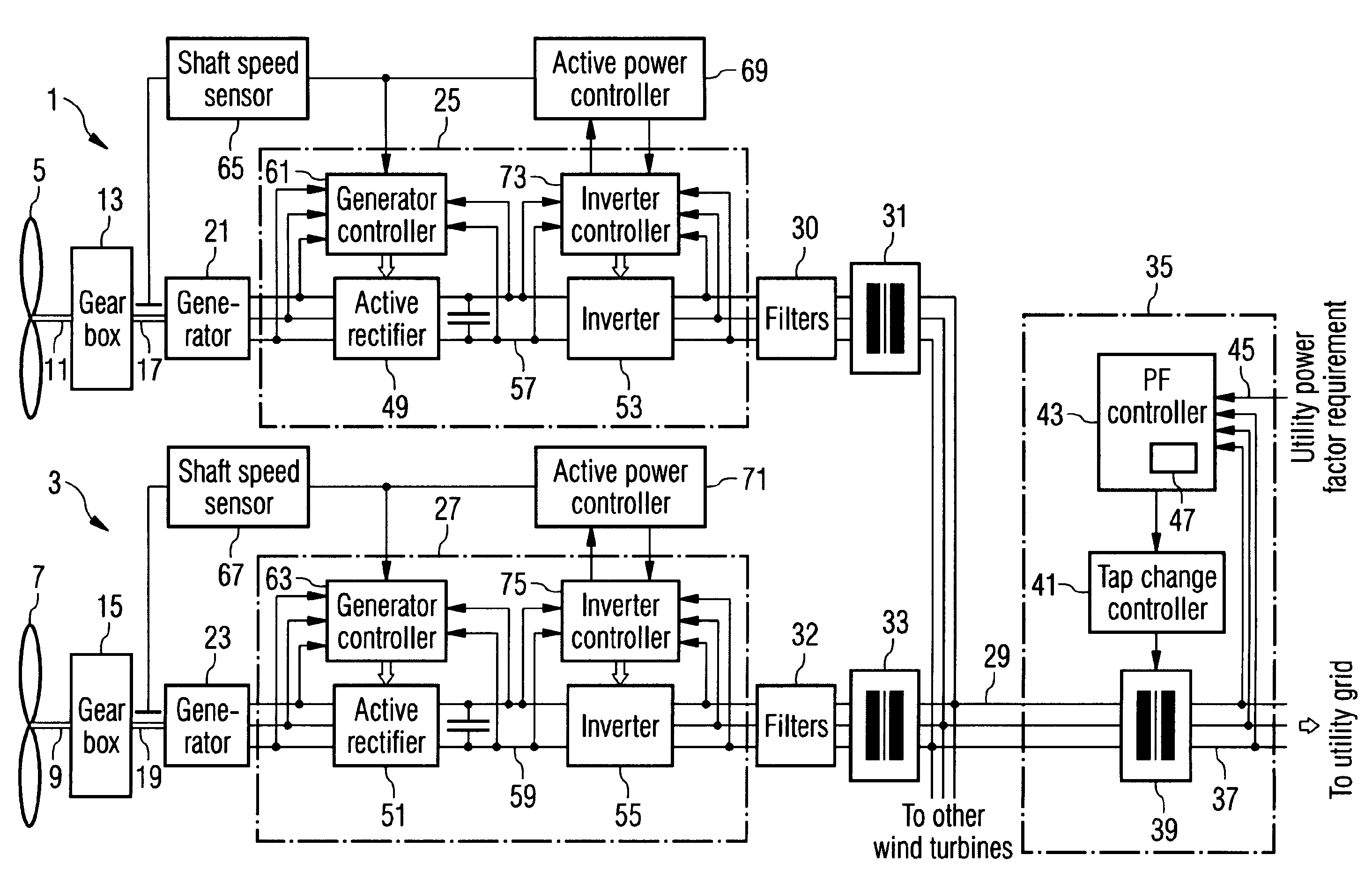
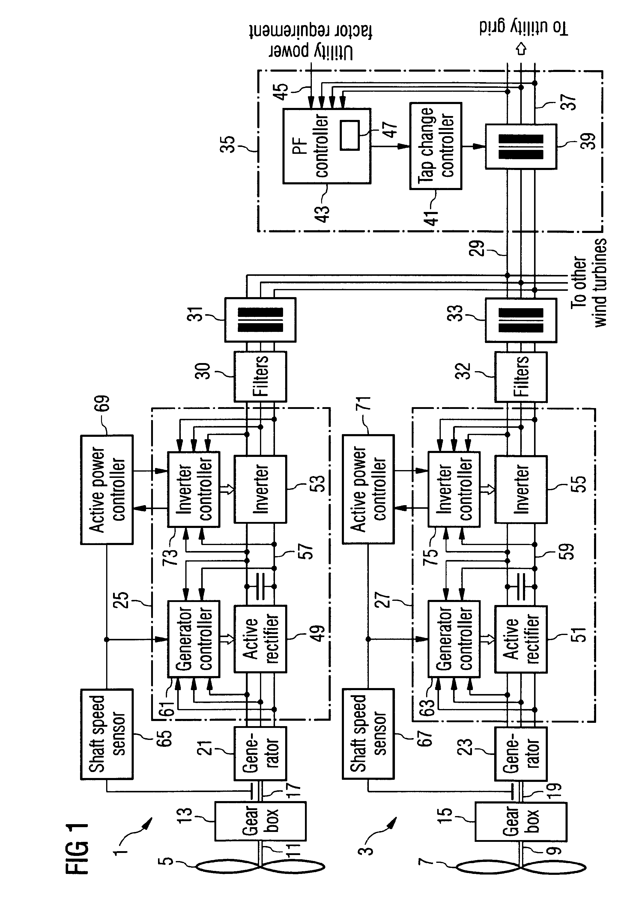
[0041]FIG. 1 shows a wind farm arrangement for carrying out a power factor control according to the invention. The wind farm is indicated by two wind turbines 1, 3, each comprising a rotor with a rotor shaft transmitting the rotational momentum of the turning rotor 5, 7 to a gear box 13, 15. In the gear box 13, 15, a transmission of the rotation to an output shaft 17, 2519 with a certain transmission ratio takes place.

[0042]The output shaft 17, 19 is fixed to the rotor of an AC generator 21, 23 which transforms the mechanical power provided by the rotation of the output shaft 17, 19 into the electrical power. The AC generator may either be a synchronous generator or an asynchronous generator. In a synchronous generator, the rotor rotates with the same rotational frequency as a rotating magnetic field produced by a stator of the generator. In contrast, in an asynchronous generator, the rotational frequencies of the stator's magnetic field and the rotor are different. The difference i...


PUM


Abstract

A method for controlling dynamic power factor or the reactive power of a wind farm is provided. The wind farm comprises a number of wind turbines connected to a utility grid driven with a requested power factor or a requested reactive power. The wind turbine output voltage is controlled to a specific voltage set point. In the method, the wind farm power factor is measured and compared with the power factor requested for the utility grid, or the wind farm reactive power is measured and compared with the reactive power requested for the utility grid, respectively; the ratio of the wind farm voltage to the utility grid voltage is adjusted, and the output voltage of the individual wind turbines is regulated to correspond to the specific voltage set point; the steps are repeated until the power factor of the wind farm electricity corresponds to the requested reactive power.

Description

CROSS REFERENCE TO RELATED APPLICATIONS[0001]This application is the US National Stage of International Application No. PCT / EP2006 / 004823, filed May 12, 2006 and claims the benefit thereof. The International Application claims the benefits of European application No. 05010542.8 filed May 13, 2005, and the benefits of American application 60 / 680,812 filed May 13, 2005, all of the applications are incorporated by reference herein in their entirety.FIELD OF INVENTION[0002]The present invention relates to a wind farm comprising a number of wind turbines connected to a Utility grid, which is to be driven with a requested power factor or a requested reactive power, and to a method of Controlling the dynamic power factor or reactive power of the wind farm.BACKGROUND OF THE INVENTION[0003]Over the last decade the fraction of energy added to power grids by wind farms has increased significantly. Therefore, there is also an increased need for Controlling wind farms delivering energy to Utilit...

Claims


Application Information

Patent Timeline
IPC IPC(8): H02P9/04
CPCH02J3/1835H02J3/1878Y02E40/30H02M7/5395Y02E10/763H02J3/386H02J3/38H02J2300/28H02J3/381Y02E10/76
Inventor STIESDAL, HENRIK
Owner SIEMENS GAMESA RENEWABLE ENERGY AS
Why Eureka
Try Eureka