Flatbed extender system for a vehicle
- Summary
- Abstract
- Description
- Claims
- Application Information
AI Technical Summary
Benefits of technology
Problems solved by technology
Method used
Image

Examples
Embodiment Construction
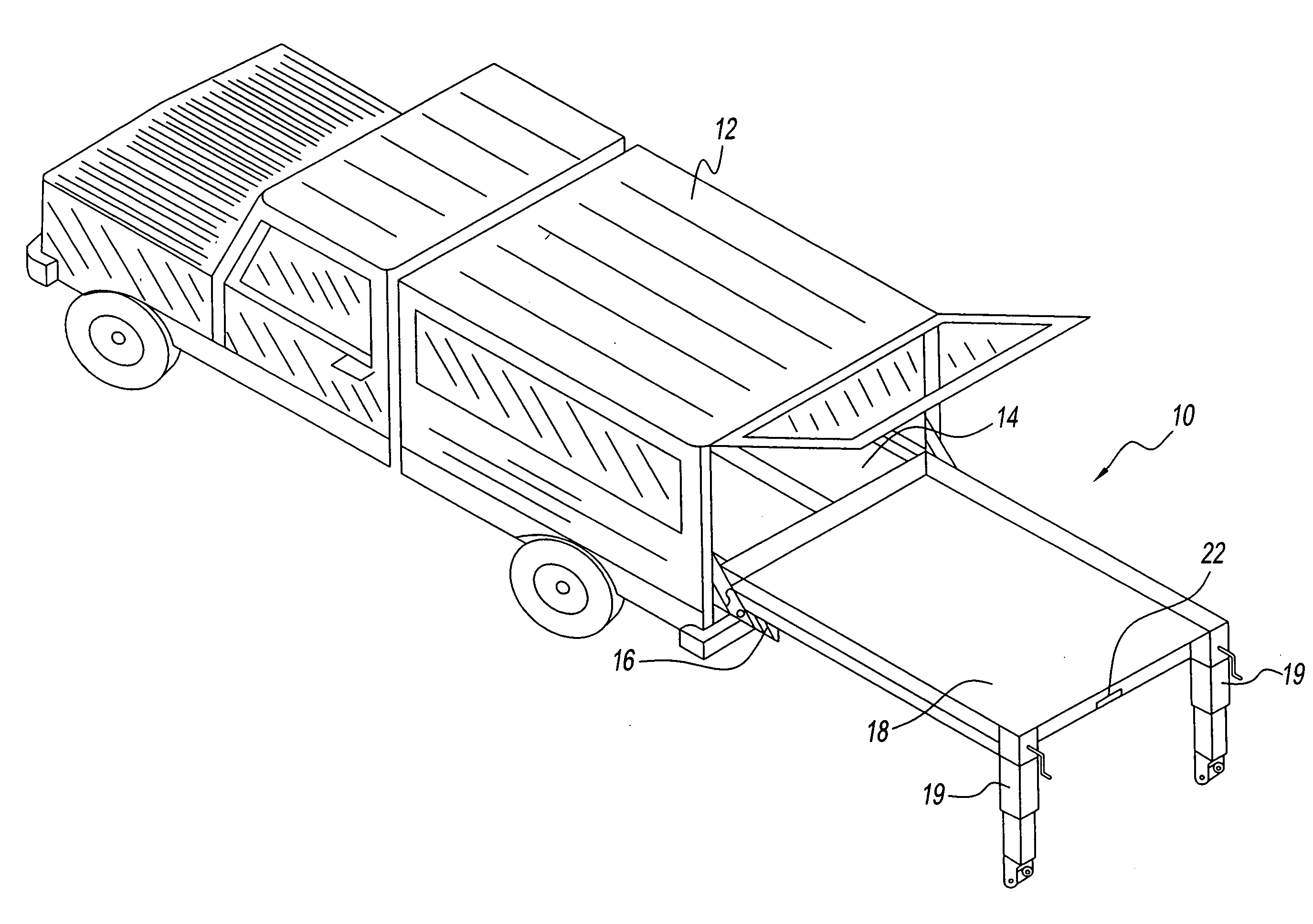
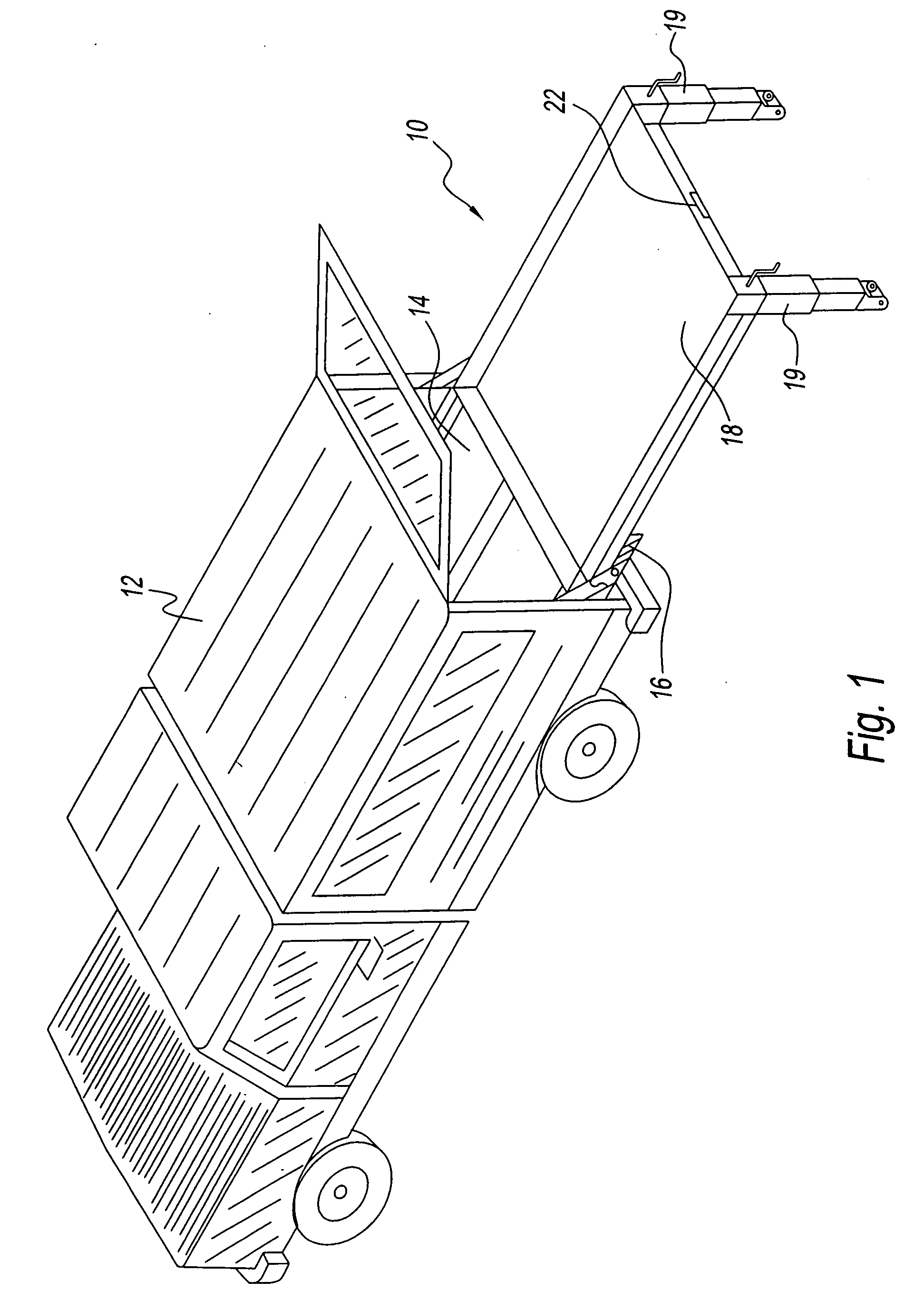
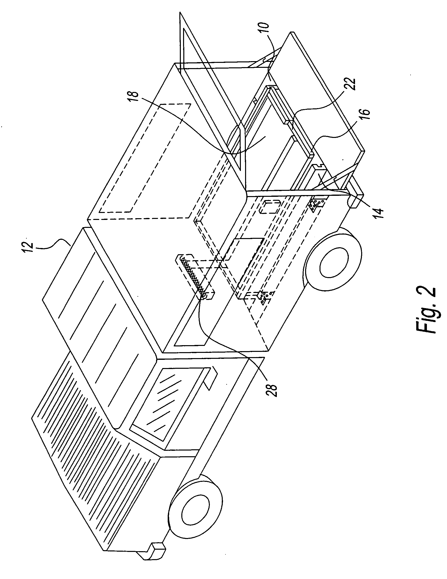
[0027]Referring to the drawings and particularly to FIG. 1, there is illustrated an extender bed system 10 according to the present invention generally represented by reference numeral. Extender bed system 10 has a channel 14 and a cradle 16 that is slidingly received in channel 14. Cradle 16 sliding receives an extender bed 18 that is free to move in and out of the cradle 16 during use. A pair of legs 19 are extendable from a forward edge 22 of extender bed 18 to provide support to bed when it is extended from vehicle 12, as shown. Legs 19 are preferably hinged to bed 18 to facilitate folding behind bed. Extender bed system 10 is shown as being connected to a passenger pick-up vehicle 12. However, the present invention can be used in conjunction with a vehicle of any size that has a flatbed ranging from the size of a hatch-back vehicle to a commercial sized moving vehicle or van for national moves. Flatbed extender system 10 is shown in FIG. 2, in the retracted position in which be...
PUM
 Abstract
Description
Claims
Application Information