Dual beam sector antenna array with low loss beam forming network

a beam forming network and dual beam technology, applied in antenna arrays, antennas, electrical equipment, etc., can solve the problems of increasing the difficulty of providing the desired antenna performance, increasing the cost of such applications, and affecting the weight and size of antennas

Active Publication Date: 2009-04-16
INTEL CORP
View PDF8 Cites 20 Cited by
  • Summary
  • Abstract
  • Description
  • Claims
  • Application Information

AI Technical Summary

Benefits of technology

[0008]In a first aspect the present invention provides an antenna array comprising first, second and third generally planar reflectors each having one or more radiators coupled thereto, the second reflector configured adjacent to and between the first and third reflectors. The first and thi

Problems solved by technology

Providing an antenna array with a number of antenna elements in a typical cellular installation can create problems related to antenna weight and size.
Also, cost is

Method used


Image

  • Dual beam sector antenna array with low loss beam forming network
  • Dual beam sector antenna array with low loss beam forming network
  • Dual beam sector antenna array with low loss beam forming network

Examples


Embodiment Construction

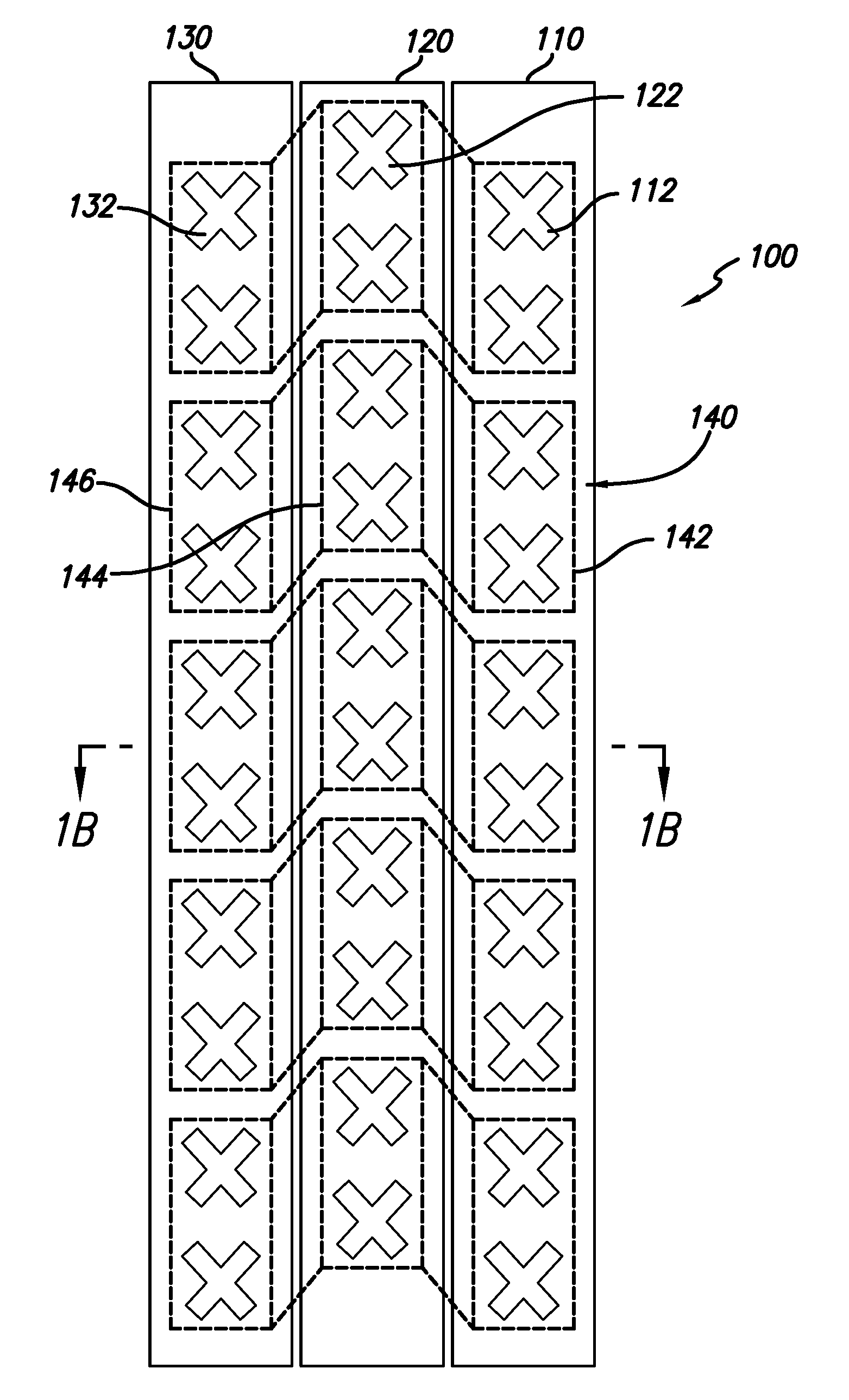
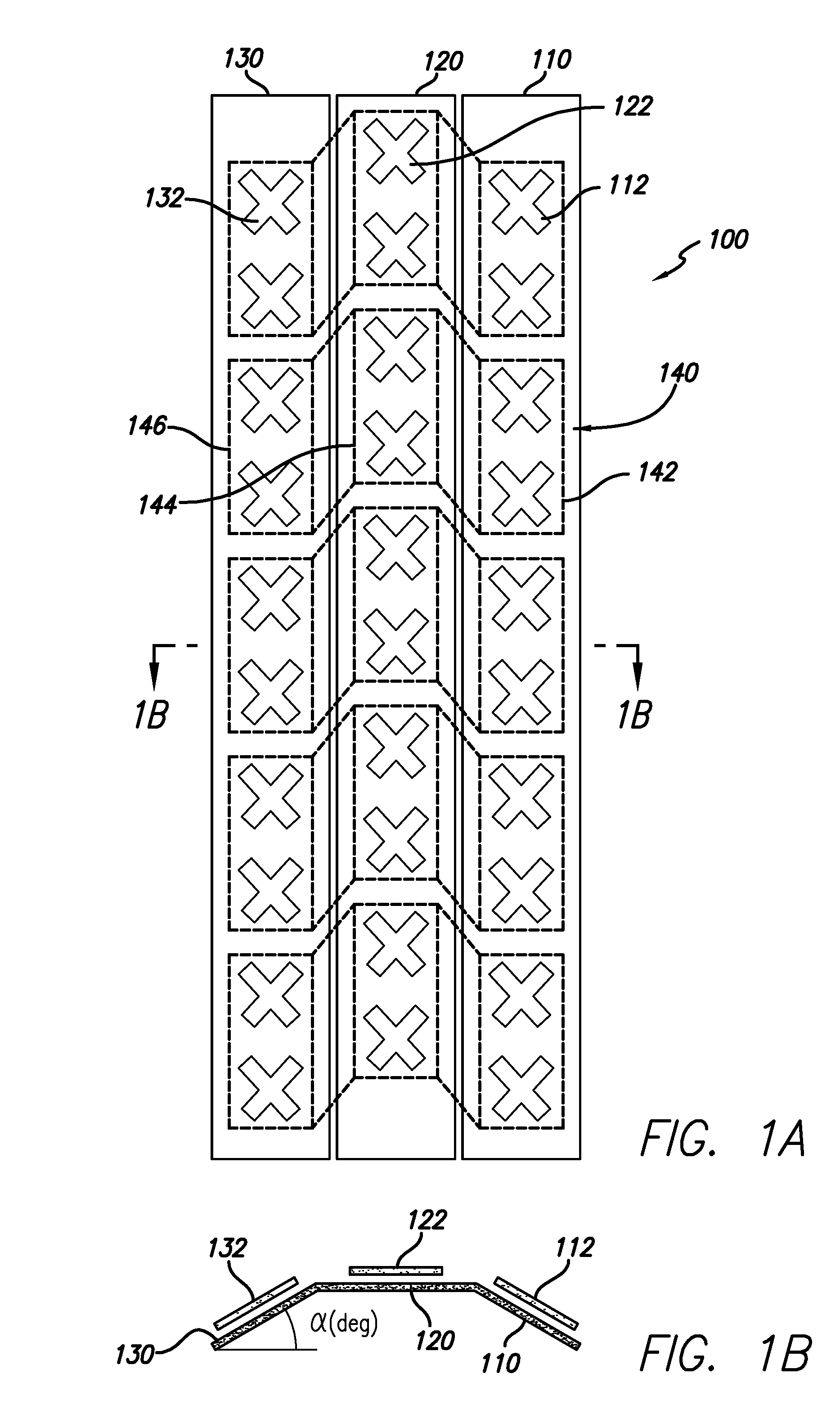
[0022]FIGS. 1A and 1B show the structure of a preferred implementation of a dual beam sector antenna array 100 in accordance with the invention. As shown in FIG. 1A, radiators 112, 122 and 132 are mounted on three separate planar reflector panels 110, 120, 130 to form a non-planar three-column antenna array. For example the radiators 112, 122 and 132 may be aperture slot coupled patch antenna elements as generally shown. Other radiators may also be employed such as planar dipole, etc. as well known in the art. The relative slope of the two edge columns, α, with respect to the center column, shown in FIG. 1B, is important in achieving the required pattern shapes and minimum cross-over and beam-split losses. Typically, a preferred range for this angle is between 20 deg to 30 deg with respect to the center column panel 120. A beam forming network described below creates dual beam radiation patterns from the three column radiator structure. The dual beam patterns can be maintained over ...


PUM


Abstract

A low loss beam forming method and antenna structure are disclosed. The method and structure may preferably be used in forming two narrow beams within a cellular sector. This method allows an increase in the overall network capacity by using a three-column non-planar array and a compact, low-cost, low-loss 3-to-2 Beam-Forming Network (BFN). This structure produces two symmetrical beams with respect to the azimuth boresight. Radiation patterns of the two beams are designed to cover the entire azimuth coverage angle of a cellular sector with minimum beam-split loss and cross-over losses.

Description

RELATED APPLICATION INFORMATION[0001]The present application claims priority under 35 USC section 119(e) to U.S. provisional patent application Ser. No. 60 / 999,182 filed Oct. 16, 2007, the disclosure of which is incorporated herein by reference in its entirety.BACKGROUND OF THE INVENTION[0002]1. Field of the Invention[0003]The present invention relates in general to radio communication systems and components. More particularly the invention is directed to antenna elements and antenna arrays for radio communication systems.[0004]2. Description of the Prior Art and Related Background Information[0005]Modern wireless antenna implementations generally include a plurality of radiating elements that may be arranged to provide a desired radiated (and received) signal beam width and azimuth scan angle. For a common three sector cellular coverage implementation each antenna will have a 65 degree (deg) azimuthal coverage area. It is desirable to achieve a near uniform beam pattern that exhibi...

Claims


Application Information

Patent Timeline
IPC IPC(8): H01Q21/00
CPCH01Q3/40H01Q25/00H01Q19/18
Inventor VASSILAKIS, BILLFOO, SENGLEE
Owner INTEL CORP
Why Eureka
Try Eureka