Ink jet recording head

a recording head and jet technology, applied in the field of jet recording head, can solve the problems of increasing increasing the amount of heat generation, increasing the difference in temperature between the recording element substrates, etc., and achieves the effect of reducing the thickness of the recording head, reducing the thickness of the recording element substrate, and simple constitution

Active Publication Date: 2009-04-16
CANON KK
View PDF9 Cites 18 Cited by
  • Summary
  • Abstract
  • Description
  • Claims
  • Application Information

AI Technical Summary

Benefits of technology

[0024]According to the present invention, it is possible to suppress an increase in temperature gradient in recording element substrate and increases in diff

Problems solved by technology

With higher-speed recording, the number of ejections of ink from one nozzle per unit time is increased, thus increasing electric energy consumption.
For this reason, thermal imbalance such that a more downstream recording element substrate is liable to be higher in temperature occurs and is more noticeable with higher-speed recording leading to increase the amount of heat generation, so that a difference in temperature between the recording element substrates is increased.
As described above, when the temperature difference between the recording element substrates is increased, a difference in ejection amount, i.e., a difference in density is also increased, thus adversely affecting a recording quality.
Therefore, in order to realize the high-speed recording while retaining th

Method used


Image

  • Ink jet recording head
  • Ink jet recording head
  • Ink jet recording head

Examples


first embodiment

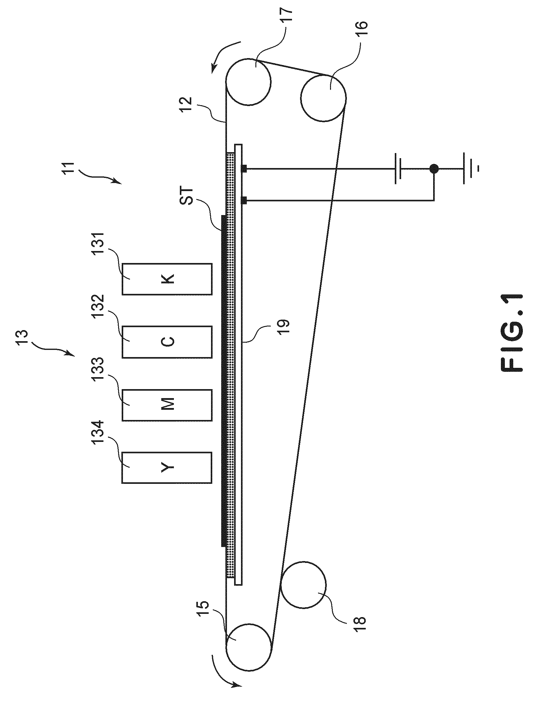
[0035]In the following embodiments, as an example of a recording apparatus using an ink jet recording method, a printer will be described.

[0036]Herein, “recording” (also referred to as “print”) represents not only formation of significant information such as a character or graphics but also formation of an image, a pattern, or the like on a recording medium, irrespective of significance or insignificance or processing of a medium.

[0037]The recording medium refers to not only paper used in a general recording apparatus but also various ink-receivable materials such as clothes, plastics, metal plates, ceramics, woods, and leathers.

[0038]The ink (also referred to as a “liquid”) is widely interpreted similarly as in the definition of the recording (print). That is, the “ink” represents a liquid subjected to formation of an image, a pattern, or the like, processing of a recording medium, or processing of ink (e.g., coagulation or insolubilization of a colorant in ink to be provided onto ...

second embodiment

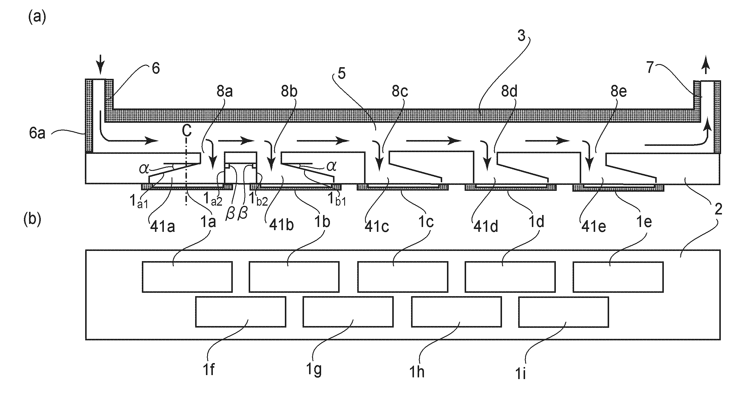
[0062]FIG. 4 illustrates a schematic structure of a full-line type ink jet recording head of this embodiment and includes a sectional view and a bottom view. A recording head in FIG. 4 is identical to any one of the recording heads 131 to 134 shown in FIG. 1 or FIG. 2. In the following, a constitution similar to that in First Embodiment will be omitted from description.

[0063]Referring to FIG. 4, individual liquid chambers 42a and 42e located at both end portions of the ink jet recording head of this embodiment, i.e., located upstreammost and downstreammost with respect to the flow direction have an asymmetric configuration with respect to a center line C of an associated recording element substrate 1a or 1e.

[0064]On the other hand, individual liquid chambers 42b, 42c and 42d sandwiched between the individual liquid chambers 42a and 42e have a symmetrical configuration with respect to a center line C of an associated recording element substrate 1b, 1c or 1d. That is, ink inlet ports...

third embodiment

[0070]FIG. 6 illustrates a schematic structure of a full-line type ink jet recording head of this embodiment and includes a sectional view (FIG. 6(a)) and a bottom view (FIG. 6(b)). A recording head in FIG. 6 is identical to any one of the recording heads 131 to 134 shown in FIG. 1 or FIG. 2. In the following, a constitution similar to that in First Embodiment will be omitted from description.

[0071]In this embodiment, individual liquid chambers 43a to 43e have axially symmetrical configuration with respect to a center line C of the individual liquid chamber 43c. That is, the individual liquid chambers 43a and 43e are axially symmetrical and the individual liquid chambers 43b and 43d are axially symmetrical. For this reason, in the individual liquid chambers 43a to 43e, the ink flow passage from an associated ink inlet port to a nozzle located upstream with respect to the flow direction is equal to the ink flow passage from an associated ink inlet port to a nozzle located downstream ...


PUM


Abstract

An ink jet recording head is constituted by a plurality of recording element substrates each including at least one nozzle array having a plurality of nozzles for ejecting ink and heat generating resistors for ejecting the ink by thermal energy, a common liquid chamber having an introducing port for supplying the ink to the nozzles and a discharging port for discharging the introduced ink outside the ink jet recording head, and a supporting member on which the recording element substrates are mounted and in which a plurality of individual liquid chambers for supplying the ink to associated ones of the recording element substrates and a plurality of ink inlet ports for supplying the ink from the common liquid chamber to associated ones of the individual liquid chambers are formed. The individual liquid chambers are arranged in a direction of flow of the ink flowing from the ink introducing port toward the discharging port. At least in an upstreammost individual liquid chamber with respect to the direction, a center line of an associated inlet port with respect to the direction is located downstream of a center line of with respect to the direction.

Description

FIELD OF THE INVENTION AND RELATED ART[0001]The present invention relates to an ink jet recording apparatus and a control method of the ink jet recording apparatus and particularly relates to an ink jet recording head for ejecting ink by utilizing thermal energy generated from a thermal energy transducer. More specifically, the present invention relates to a recording head structure for suppressing a difference in temperature, between a plurality of recording element substrates, of ink to be supplied to the plurality of recording element substrates mounted in a full-line type recording head.[0002]An ink jet recording apparatus of a type in which a plurality of recording heads each including a plurality of recording elements is fixed in parallel with each other and a recording medium is scanned with the recording heads to effect recording. The ink jet recording apparatus of this type is characterized by a recording speed higher than that of a so-called serial scanning type ink jet re...

Claims


Application Information

Patent Timeline
IPC IPC(8): B41J2/05
CPCB41J2/1408B41J2202/20B41J2/155
Inventor CHINO, NORIYUKIKANEMURA, SHOJINOMURA, HIROYASU
Owner CANON KK
Why Eureka
Try Eureka