Variable geometry turbine

a turbine and variable geometry technology, applied in the direction of combination engines, motors, engine fuctions, etc., can solve the problems of significant disturbance of fluid flow, pressure wave generation, and other problems, and achieve the effect of reducing the number of turbines

Inactive Publication Date: 2009-04-16
FPT MOTORENFORSCHUNG
View PDF4 Cites 13 Cited by
  • Summary
  • Abstract
  • Description
  • Claims
  • Application Information

AI Technical Summary

Benefits of technology

[0011]According to the present invention, the problems exposed above have been solved by applying a generou

Problems solved by technology

The pressure waves otherwise could generate vibration wear on the whole VGT actuating mechanism, and on other members such as seals and bushings.
Moreover, the pressure waves can provoke significant oscillation of the actuating mechanism, at least with certain types of actuators, in particular pneumatic and electric ones.
This includes the disadvantage that the balance holes cause considerable disturbance to the fluid flow through the nozzle gap.
Reducing the nozzle gap, respectively narrowing the fluid passage between consecutive vanes, increases the interference of the holes with the fluid flow.
In such condition, the balance holes represent significant sinks for the flow, leading to a expansion of the fluid flow into the holes, in turn the downstream edges of the balance h

Method used


Image

  • Variable geometry turbine
  • Variable geometry turbine
  • Variable geometry turbine

Examples


Embodiment Construction

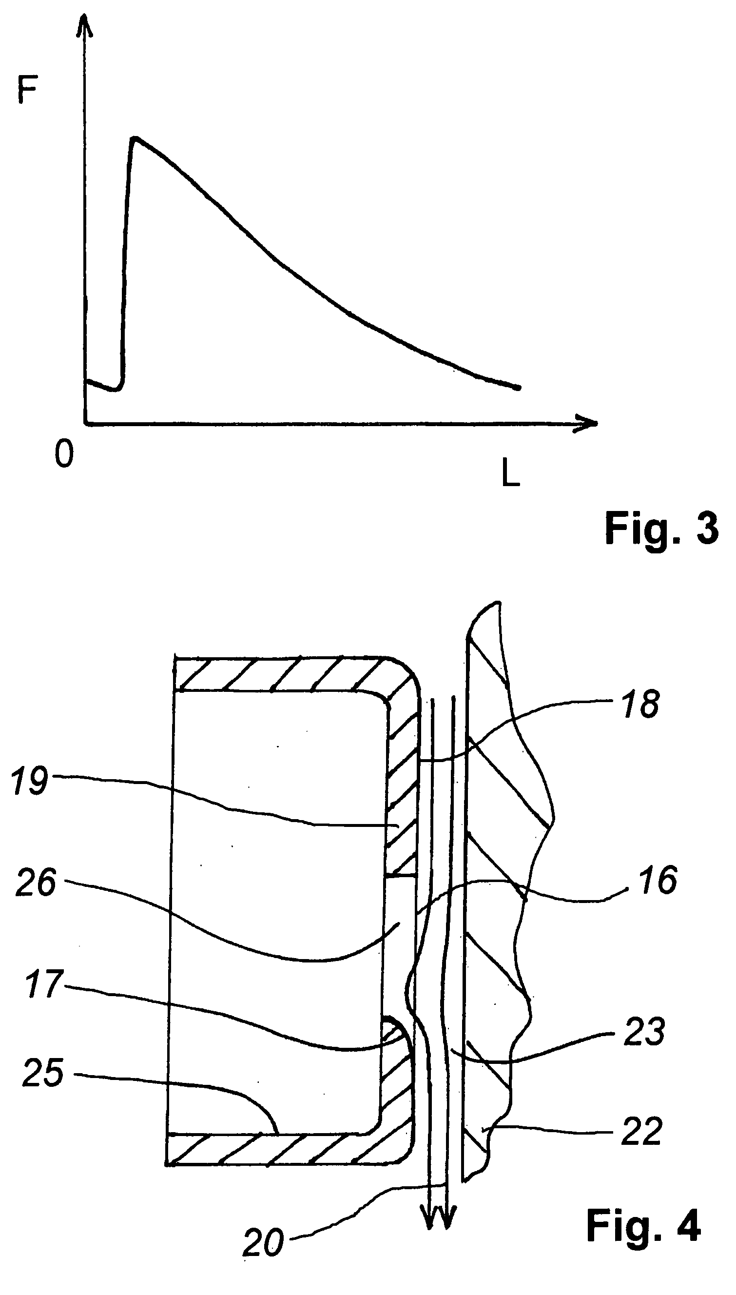
[0025]The VGT according to the present invention can be designed and manufactured in a similar way as the one of prior art described above, except for the shape of the balance hole muzzles. FIG. 4 shows a detail section according to a plane parallel with the flow lines of the fluid through the nozzle gap (depending on the inclination of the vanes) of a VGT according to the present invention; the axially adjustable ring 25 is shown at minimum nozzle gap, and the flow from the inlet scroll to the turbine rotor is schematically indicated by the arrows 20. A balance hole 26 is provided in wall 19, whose surface 18 faces the nozzle gap 23. The edge 16, delimiting the hole 26 from the surface 18 presents a rounded portion, downstream the hole with respect to the fluid flow.

[0026]According to a preferred embodiment not all of the edge is rounded off, nor is the rounding curvature deploying uniformly. The curvature radius of the edge can gradually vary from 0 (sharp edge) or from a minimum ...


PUM


Abstract

Variable geometry turbine, in particular a gas turbine, comprising a housing (2, 22), a turbine rotor (4), a fluid inlet scroll (1) that surrounds said turbine rotor, a vaned nozzle interposed between said inlet scroll and said turbine rotor conceived to accelerate the flow of fluid, said nozzle comprising an axially adjustable ring (5, 25) conceived to vary the nozzle gap (3, 23) and having a wall (19) delimiting said nozzle gap, said wall having balance holes (6, 26, 26′) connecting the nozzle gap with a chamber (12) delimited by said housing and said ring, characterised in that the edges (16), formed by said holes with the surface (18) of said wall facing the nozzle gap, are rounded in the portion (17, 17′) located downstream the holes with respect to the fluid flow.
Turbocharger and supercharged engine comprising said turbine.

Description

CROSS-REFERENCE TO RELATED APPLICATIONS[0001]Not ApplicableSTATEMENT RE: FEDERALLY SPONSORED RESEARCH / DEVELOPMENT[0002]Not ApplicableBACKGROUND[0003]1. Field of the Invention[0004]The present invention concerns a variable geometry turbine, in particular for a turbocharger for a supercharged internal combustion engine, and said turbocharger and engine.[0005]2. Prior Art[0006]Known variable geometry turbines (VGT) have a drive fluid inlet in form of a scroll surrounding the turbine rotor, and a vaned annular nozzle located between said inlet scroll and the turbine rotor. On VGT's of the “moving wall” type, the nozzle gap is axially adjustable to control the power of the turbine and, in case of VGT turbochargers for supercharged internal combustion engines, the back pressure at the exhaust manifold of the engine (this is particularly useful when used as exhaust brake).[0007]FIG. 1 shows a typical “moving wall” VGT. The figure represents a longitudinal section, according to a plane cont...

Claims


Application Information

Patent Timeline
IPC IPC(8): F01D17/16
CPCF01D17/143F02C6/12F05D2220/40F05D2260/96F05D2250/16F05D2250/193F05D2250/62F05D2250/70F05D2250/71F05D2250/14F05D2250/192F05D2250/19
Inventor SPULER, JUERG
Owner FPT MOTORENFORSCHUNG
Why Eureka
Try Eureka