Cranked Rod Pump Apparatus And Method

a pumping apparatus and crank rod technology, applied in the direction of piston pumps, positive displacement liquid engines, borehole/well accessories, etc., can solve the problems of inability to use a walking beam apparatus or other known types of prior pumping apparatus and methods, inability to control, and inability to achieve the effect of enhancing the alignment of various moving parts

Active Publication Date: 2009-04-16
UNICO LLC
View PDF18 Cites 29 Cited by
  • Summary
  • Abstract
  • Description
  • Claims
  • Application Information

AI Technical Summary

Benefits of technology

[0011]In some forms of the invention, the cranked rod mechanical actuator may further include a pneumatic counterbalance arrangement operatively connected between the frame and the vertically moveable member. The pneumatic counterbalance arrangement may include at least one pneumatic cylinder that is operatively connected between the base and the vertically moveable member, for storing energy during a portion of the downward stroke of the vertically moveable member and for releasing the stored energy during a portion of a subsequent upward stroke of the vertically moveable member. In some forms of the invention, at least one pneumatic cylinder may be disposed between the vertically moveable member and the base, to thereby provide a physically compact apparatus, and to more advantageously align the pneumatic cylinder to apply force between the vertically moveable member in the base in a direct rather than an offset manner.
[0012]In some forms of the invention, the articulating link element may be configured to include an offset section thereof, to thereby enhance alignment of various moving parts of the CRP apparatus with one another.

Problems solved by technology

As discussed at length in commonly assigned co-pending U.S. patent application Ser. No. 11 / 761,484, titled “Linear Rod Pump Apparatus And Method,” by Beck et al., conventional walking beam apparatuses have a number of disadvantages, not the least of which is their large size.
In addition, performance of the walking beam pump apparatus is largely a function of the design in connection of a number of mechanical parts, which include massive counter-weights and complex drive mechanisms which are difficult to control for obtaining maximum pumping efficiency or to compensate for changes in the condition of the well over time.
Also, for potential well sites in very remote locations, and particularly in locations without access to a power grid and no practical road access for regularly servicing a pumping apparatus or a motor generator, batteries, or other traditional stand-alone power source for a pumping apparatus, it has heretofore been impractical, and in some cases impossible, to utilize a conventional walking-beam apparatus or other known types of prior pumping apparatuses and methods.
As a result, potentially valuable energy resources have remained untapped.
Although the linear rod pump apparatus and methods, disclosed in the above-referenced '484 to Beck, provide significant improvement over other prior pumping apparatuses and methods in many pumping applications, the continually reversing motor utilized in the linear rod pump apparatus and methods disclosed in Beck '484 may not be desirable in some pumping applications.

Method used


Image

  • Cranked Rod Pump Apparatus And Method
  • Cranked Rod Pump Apparatus And Method
  • Cranked Rod Pump Apparatus And Method

Examples


Embodiment Construction

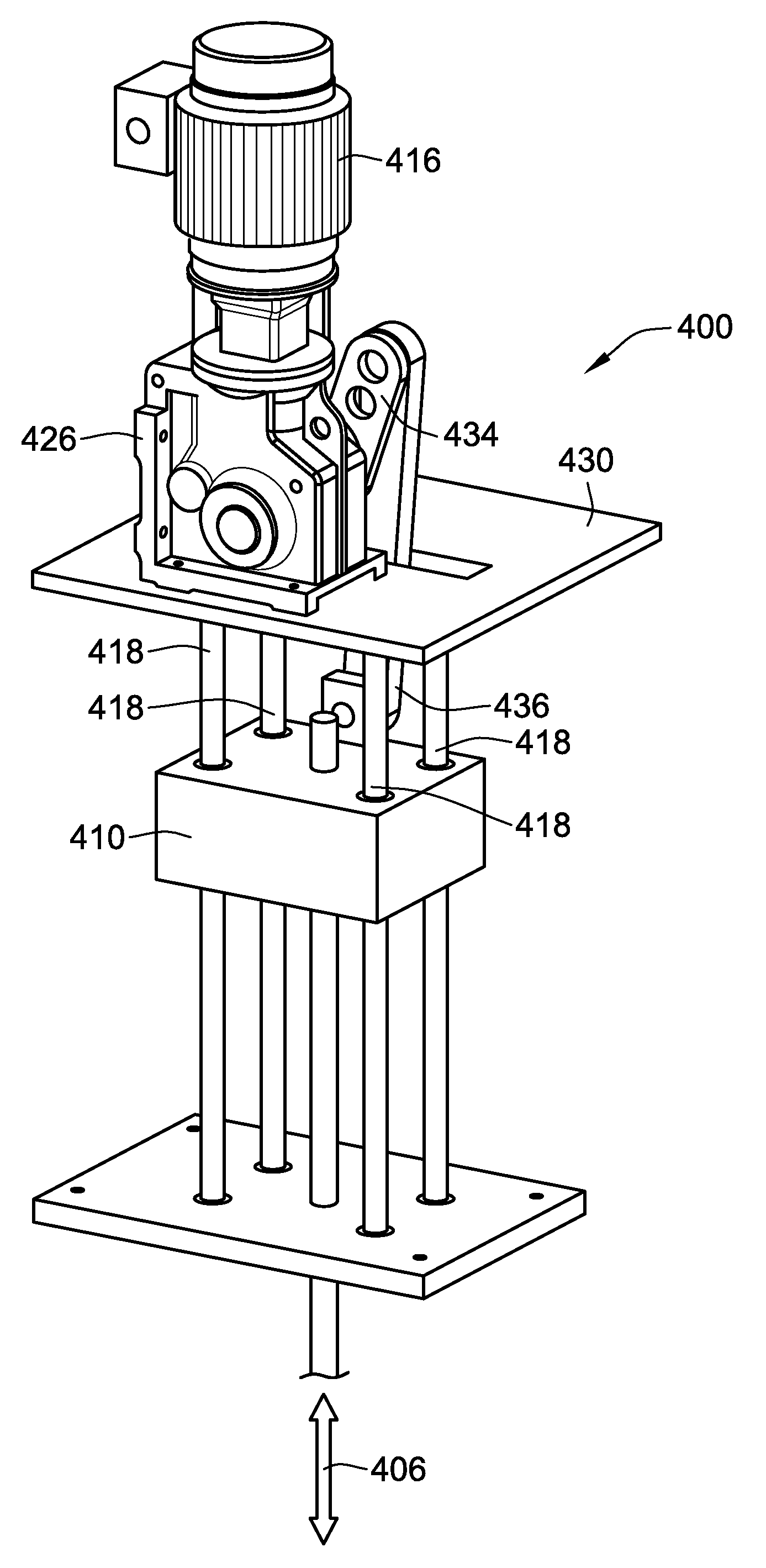
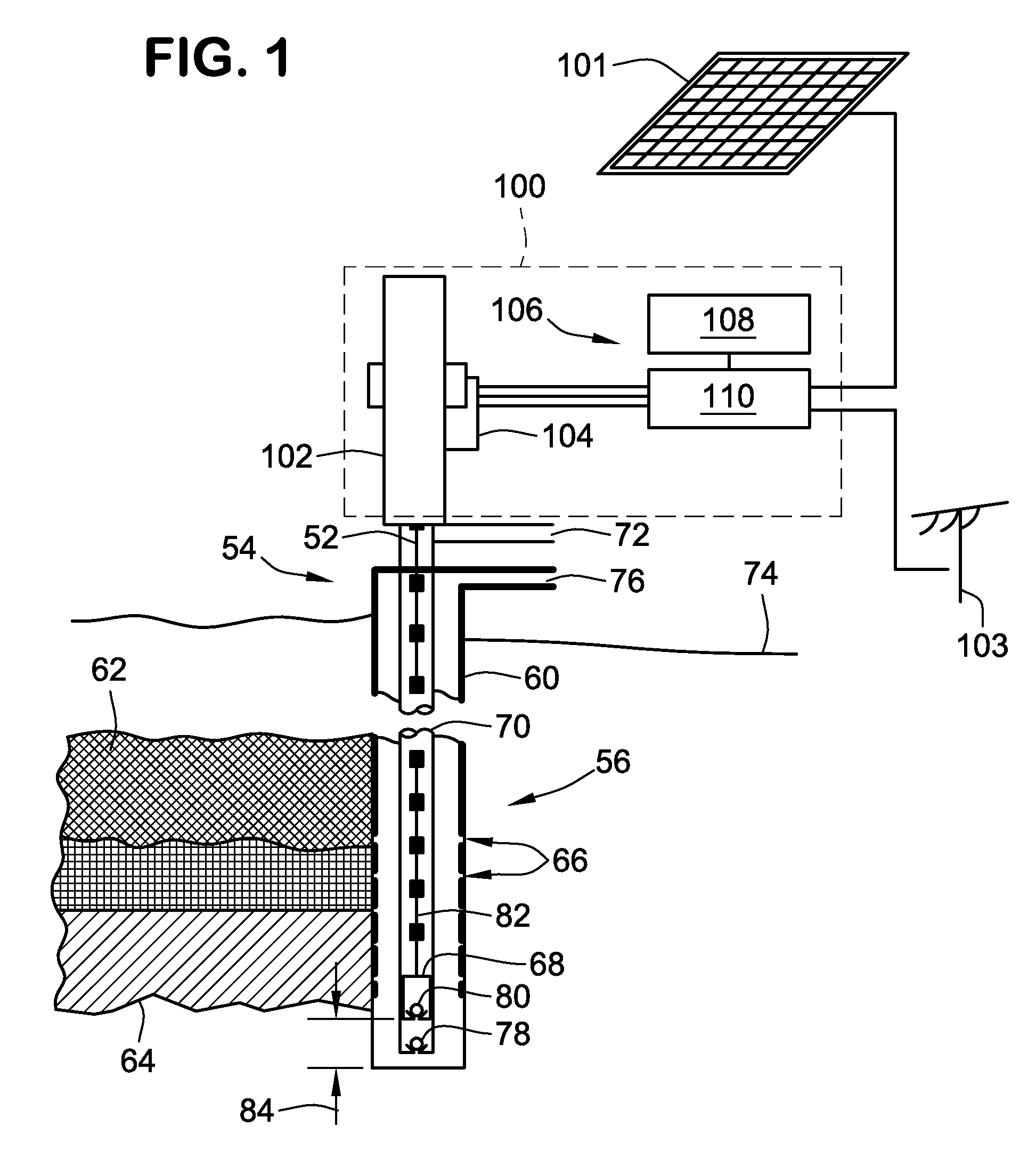
[0029]FIG. 1 is a schematic illustration showing an embodiment of a cranked rod pump (CRP) apparatus 100 attached to a wellhead of a hydrocarbon well. As shown in FIG. 1, the invention may be practiced with a variety of power sources including a solar array 101 or through attachment to a conventional power grid 103.

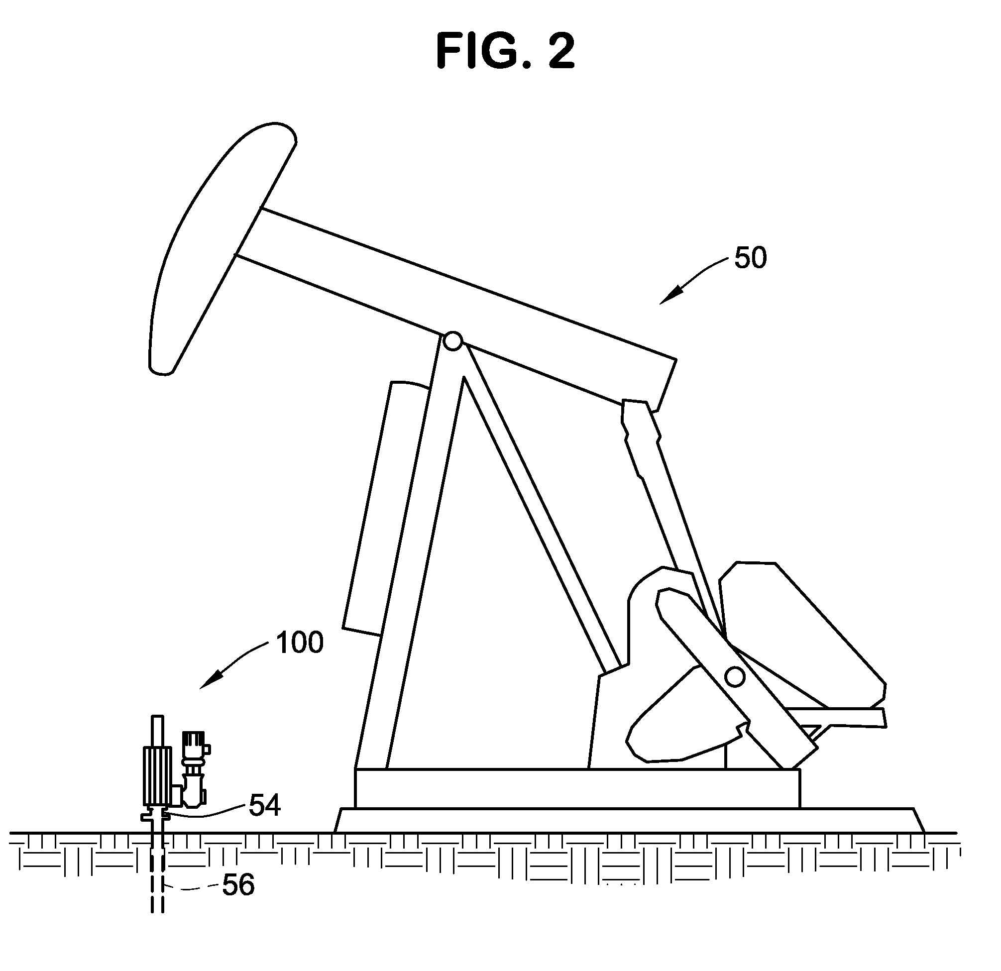
[0030]FIG. 2 illustrates the manner in which a CRP apparatus 100, according to the invention, may be utilized to great advantage for replacing a conventional walking beam pumping apparatus 50. In FIG. 2, the cranked rod pumping apparatus 100 is mounted on the well head 54 of a hydrocarbon well 56.

[0031]Returning to FIG. 1, the well includes a casing 60 which extends downward into the ground through a subterranean formation 62 to a depth sufficient to reach an oil reservoir 64. The casing 60 includes a series of perforations 66, through which fluid from the hydrocarbon reservoir enter into the casing 60, to thereby provide a source of fluid for a down-hole pumping apparatu...


PUM


Abstract

An improved apparatus and method are provided, for pumping fluids, such as water and/or hydrocarbons, from a subterranean formation or reservoir, through use of a cranked rod pumping (CRP) apparatus for imparting reciprocating substantially vertical motion to a rod of a sucker-rod pump having a pump stroke. The CRP apparatus includes a motor driven cranked mechanical actuator arrangement. The cranked mechanical actuator arrangement includes a substantially vertically moveable member attached to the rod of the sucker-rod pump for imparting and controlling vertical motion of the rod of the sucker-rod pump. The actuator arrangement may include pneumatic counterbalancing.

Description

CROSS-REFERENCE TO RELATED PATENT APPLICATIONS[0001]This patent application claims the benefit of U.S. Provisional Patent Application No. 60 / 979,986, filed Oct. 15, 2007, the entire teachings and disclosure of which are incorporated herein by reference thereto.FIELD OF THE INVENTION[0002]This invention relates to pumping of fluids, such as water and / or hydrocarbons, from subterranean formations or reservoirs, and more particularly to a pumping apparatus and method for use in such pumping applications.BACKGROUND OF THE INVENTION[0003]For many years, the familiar “horsehead” walking-beam type mechanism has been used for pumping fluids such as water and / or oil from subterranean formations. As discussed at length in commonly assigned co-pending U.S. patent application Ser. No. 11 / 761,484, titled “Linear Rod Pump Apparatus And Method,” by Beck et al., conventional walking beam apparatuses have a number of disadvantages, not the least of which is their large size. In addition, performance...

Claims


Application Information

Patent Timeline
Patent Type & Authority Applications(United States)
IPC IPC(8): F04B35/04E21B43/16
CPCE21B43/126F04B47/02Y02E10/46
Inventor BECK, THOMAS L.PETERSON, RONALD G.MACDONALD, MICHAEL A.DRY, MICHAEL D.
Owner UNICO LLC
Why Eureka
Try Eureka