Rod connection in a surgical device and rod-shaped bone stabilization device comprising the same

a bone stabilization device and surgical device technology, applied in the direction of shrinkage connection, diagnostics, applications, etc., can solve the problems of increasing relative amount of interference, requiring considerable axial forces to assemble components, etc., to reduce the force necessary, efficiently transmit the bending moment applied, and stabilize the device against bending

Inactive Publication Date: 2009-04-16
BIEDERMANN TECH GMBH & CO KG
View PDF10 Cites 21 Cited by
  • Summary
  • Abstract
  • Description
  • Claims
  • Application Information

AI Technical Summary

Benefits of technology

[0012]Accordingly, a frictional force between both wall surfaces is also reduced. Insertion of the rod part into the bore upon assembly is thus facilitated. Meanwhile, the length of the bore necessary to stably support the rod part with regard to a bending momentum can be retained. The recess provided in the inner wall surface may be formed as a homogeneously distributed pattern within the bore. In one specific embodiment, the recess is provided as an internal thread within the bore. However, it is noted that any type of recess or recesses suitable to efficiently reduce the contact surface area may be utilized with the present invention.
[0014]It is noted that the internal thread is not intended to engage with a corresponding external thread of the rod part, however, the invention shall not be limited accordingly. A thread may be easily manufactured in a controlled manner. A reduced amount of surface contact area may further be controlled without strong efforts.
[0017]The rod receiving member of the rod connection according to this aspect of the invention is rigidly fixed to the first section, while the corresponding rod part extends through the flexible section towards the second section, where it is slidably supported with its free end. The rod part serves to stabilize the device against bending and efficiently transmits the bending moments applied from externally via its fixated end in the bore of the rod receiving member and via the guiding support at its free end. Thereby, the full length of the bore is retained to provide sufficient support while the recess serves to reduce the forces necessary to insert the rod part in bore.

Problems solved by technology

Consequently, with decreasing sizes of the diameters, the relative amount of interference increases.
As a result, there is a tendency to provide rod connections in clinical surgery, which may require considerable axial forces to assemble the components.

Method used


Image

  • Rod connection in a surgical device and rod-shaped bone stabilization device comprising the same
  • Rod connection in a surgical device and rod-shaped bone stabilization device comprising the same
  • Rod connection in a surgical device and rod-shaped bone stabilization device comprising the same

Examples


first embodiment

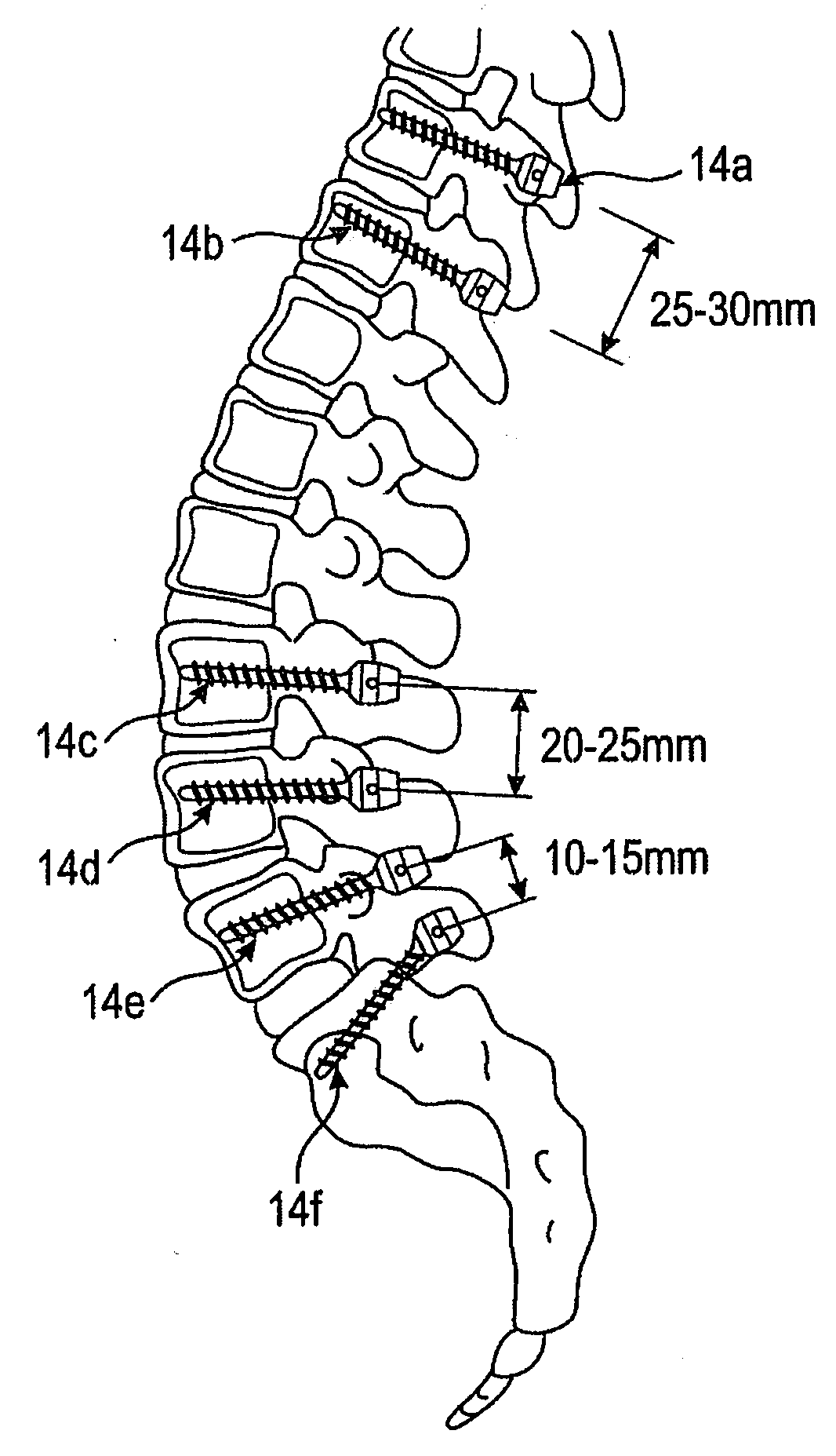
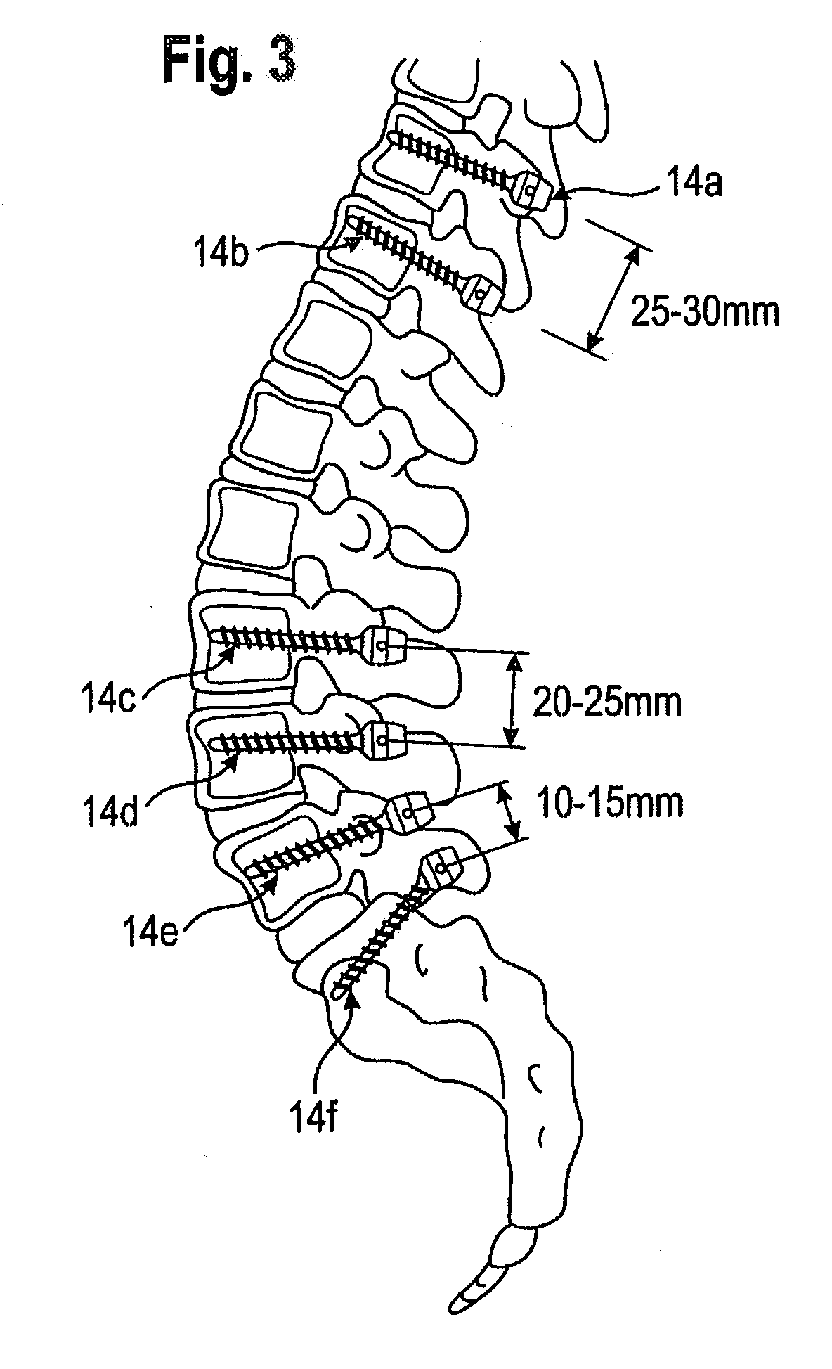
[0042]A first embodiment concerning a bone stabilization device is detailed with regard to FIGS. 3-8. FIG. 3 shows a lower part of the spine anatomy in conjunction with variously positioned bone fixation elements 14a-14f. The bone fixation elements include a bone anchoring element such as a bone screw and a receiving part for receiving and fixing, e.g., a head portion of the bone screw. Each of the bone fixation elements 14a-14f is anchored in one vertebrae of either the thoracic or lumbar spine.

[0043]A bone stabilization device may include a rod device 16 (not shown in FIG. 3) which connects at least two of the bone fixation elements 14a-14f. As shown in the partial views of FIGS. 4, 5A and 5B, the rod includes a first section 20, a second section 22 and a flexible section 24 extending between the sections 20, 22. Note that the sections 20, 22 are cut at the left and right ends, respectively, for illustration purposes. The bone fixation elements 14a-14f are arranged according to an...

second embodiment

[0056]A second embodiment will be explained with reference to FIGS. 9-12. FIG. 9 shows an angular measurement device 51 for clinical surgery applications. A shifting element 57 may be manually pushed in longitudinal direction of the main body housing 53 with an actuator (not shown). Depending on the shift position of the shifting element 57 an opening angle of plate-like members 61, 63 is achieved. Thereby, the plate-like members pivot around a shaft axis 65 held on support arms 66.

[0057]The shift position of the shifting element 57 is converted into a pivoting movement of the plate-like members 61, 63 by virtue of a connecting member 59. The connecting member 59 has a shaft hole 69 through which a shaft (not shown in FIG. 9) mounted to the shifting element 57 extends such that the connecting member 59 is rotatable relative to the shaft.

[0058]Further, as shown in FIGS. 10, 11A and 11B, the connecting member 59 has a bore 73 through which a further shaft 67 extends. The shaft 67 is p...


PUM


Abstract

A rod connection for fixing a rod part in a surgical device within a bore of a rod receiving member includes the rod receiving member having a bore having an inner diameter, the rod part having an outer diameter, the rod part being introduced into the bore, wherein the inner diameter of the bore and the outer diameter of the rod part are selected, such that the rod part is press-fitted into the bore of the rod receiving member. The bore has an inner wall surface opposing an outer wall surface of the rod part, the inner wall surface or the outer wall surface being provided with at least one recess in order to reduce a contact surface area between the rod part and the rod receiving member.

Description

CROSS-REFERENCE TO RELATED APPLICATION(S)[0001]The present application claims the benefit of U.S. Provisional Patent Application Ser. No. 60 / 979,201, filed Oct. 11, 2007, the contents of which are hereby incorporated by reference in their entirety, and claims priority from European Patent Application, 07019941.9, filed Oct. 11, 2007, the contents of which are hereby incorporated by reference in their entirety.BACKGROUND OF THE INVENTION[0002]The invention relates to a rod connection provided in a surgical device.[0003]Surgical devices may be composed of several components, which are adjoined with each other depending on the application either upon assembly of the respective device by the manufacturer or at the instance of surgery. Thus a connection between those components has to be provided, which for example secures a predetermined degree of reliability of the device in view of strain, bending and torsion stress, when this connection represents a rigid or fixed interface between t...

Claims


Application Information

Patent Timeline
Patent Type & Authority Applications(United States)
IPC IPC(8): A61B17/70A61B17/04
CPCA61B17/7004A61B17/7028F16B4/004A61B19/46A61B2019/467A61B17/705A61B90/06A61B2090/067A61B17/68A61B17/82A61B17/84
Inventor BIEDERMANN, LUTZMATTHIS, WILFRIED
Owner BIEDERMANN TECH GMBH & CO KG
Why Eureka
Try Eureka