
System and method for patient temperature control

a patient temperature and temperature control technology, applied in the field of patient temperature control, can solve the problems that the maximum effect of brain damage from a stroke or cardiac arrest may take hours to reach, and achieve the effect of facilitating enhanced reliability

Active Publication Date: 2009-04-16
MEDIVANCE
View PDF25 Cites 68 Cited by
  • Summary
  • Abstract
  • Description
  • Claims
  • Application Information

AI Technical Summary

Benefits of technology

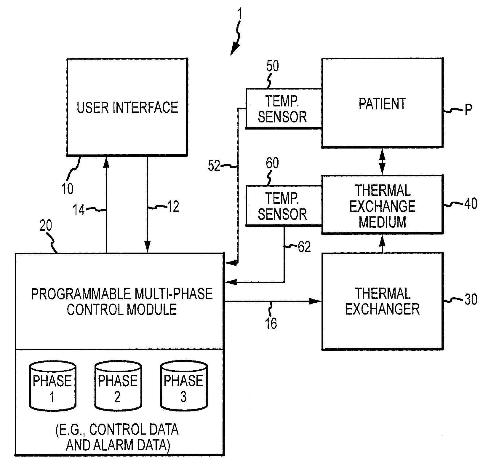
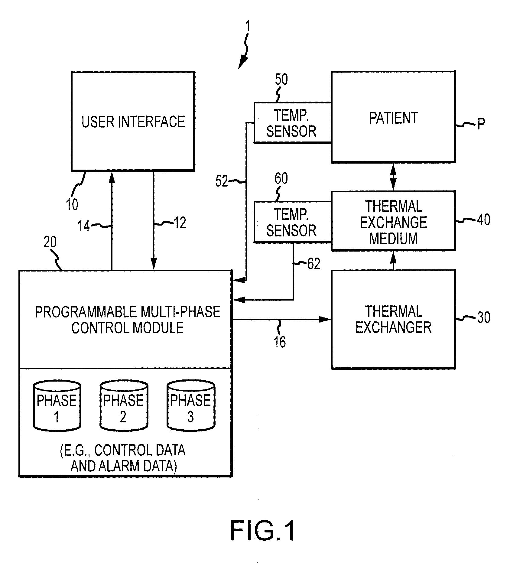
[0008]One objective of the present invention is to provide a patient temperature control system and method that facilitates enhanced reliability.
[0009]Another objective of the present invention is to provide an improved patient temperature control system and method that is user friendly.
[0010]Yet another objective of the present invention is to provide an improved patient temperature control system and method that facilitates the realization of enhanced efficiencies of medical care resources.
[0018]The user interface may be further adapted with various numerical and graphic user interface functionalities. For example, a graphic display may be provided to visually present plots of target patient temperature adjustment rates for one or more patient treatment phases, together with a plot(s) of a measured patient temperature and / or of a measured temperature of a thermal exchange medium. As may be appreciated, such visual display facilitates medical personnel monitoring of a given patient therapy procedure so as to enhance overall control and responsive action as necessary.

Problems solved by technology

In fact, brain damage from a stroke or cardiac arrest may take hours to reach maximum effect.

Method used


Image

  • System and method for patient temperature control
  • System and method for patient temperature control
  • System and method for patient temperature control

Examples


screens 204 , 206 and 208

[0053]Screens 204, 206 and 208 of FIG. 3B, FIG. 3C and FIG. 3D also provide protocol data regarding corresponding set phase durations, or remaining durations, of Phases 1-3. More particularly, in relation to “Phase 2” and “Phase 3”, the corresponding set durations of “11:00” and “04:30” are presented in the non-interactive informational region 242 of FIGS. 3B and 3C, respectively. In FIG. 3C the remaining duration of “Phase 2” is illustrated as “6:05 Hr.”, since a portion of Phase 2 has already passed (i.e. 4 hours and 55 minutes). Similarly, in FIG. 3D the remaining duration of “Phase 3” is illustrated as “00:50 Hr.”, since a portion of Phase 3 has already passed (i.e. 3 hours and 40 minutes).

[0054]With respect to FIG. 3B the corresponding phase duration for Phase 1 is a minimum amount of time entailed to lower the temperature of a given patient to the target patient temperature for “Phase 1”, i.e. 33.0° C., with the system operating at pre-set maximum rate. As such, the duration i...


PUM


Abstract

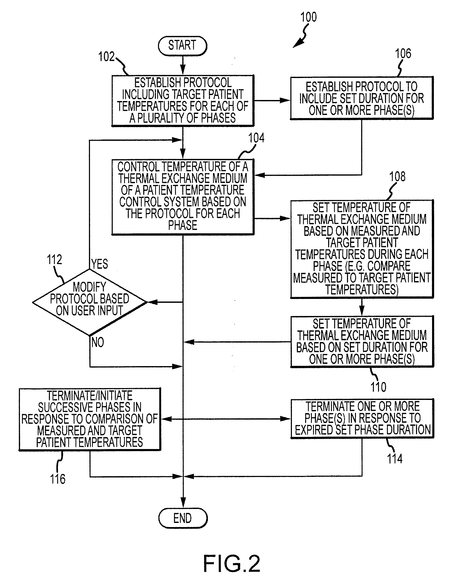
A patient temperature control system and method are provided for automated temperature control according to a programmed protocol. In one aspect, at least one programmed protocol may be established for each of a plurality of patient thermal therapy phases. In turn, the temperature of a thermal exchange medium may be controlled, based at least in part, upon the programmed protocol, during each of the phases. In another aspect, a plurality of programmed protocols may be established, wherein a selected one of the protocols (e.g. selected by a user at a user interface) may be utilized for automated temperature control during patient thermal therapy. The protocol(s) may include a target patient temperature and / or a set duration for one or more of the phase of thermal therapy. Further, the protocol(s) may be user-definable and modifiable during therapy. In a multi-phase configuration, automatic termination and initiation of successive phases may be selectively established by a user, based on target patient temperature data and / or set duration data on a phase-specific basis.

Description

RELATED APPLICATIONS[0001]This application claims priority to U.S. Patent Provisional Application Ser. No. 60 / 979,760, filed Oct. 12, 2007, entitled “SYSTEM AND METHOD FOR PATIENT TEMPERATURE CONTROL”, the entirety of which is hereby incorporated by reference.FIELD OF THE INVENTION[0002]The present invention relates to an improved system and method for patient temperature control via temperature control of a thermal exchange medium, including automated thermal control of a plurality of therapy phases based upon one or more programmed protocols.BACKGROUND OF THE INVENTION[0003]The therapeutic use of bodily cooling and heating systems, respectively, is ever-increasing. Hypothermia may occur for a variety of reasons, including exposure to cold environments, or complex surgical procedures.[0004]During surgery, a patient typically experiences mild hypothermia as a result of the effect of general anesthesia on the body's thermoregulatory system and prolonged exposure of internal organs. M...

Claims


Application Information

Patent Timeline
Patent Type & Authority Applications(United States)
IPC IPC(8): A61F7/00
CPCA61B19/56A61F2007/0093A61F2007/0086A61F7/0085A61B34/25A61F2007/0096A61F2007/0054A61F2007/0095A61F7/00
Inventor CARSON, GARY A.GRUSZECKI, GARYPROCTOR, ROBERT
Owner MEDIVANCE
Learn More