
Distributed Physics Based Training System and Methods

a distributed physics and training system technology, applied in the field of simulators, can solve the problems of communication delay, human-in-loop (hil) entities tending to complicate matters even more, and ensuring that each simulator receives and responds to all pdus from all other simulators, so as to reduce the training value of the simulation and reduce the realism

Active Publication Date: 2009-04-16
CAE USA INC +1
View PDF9 Cites 71 Cited by
  • Summary
  • Abstract
  • Description
  • Claims
  • Application Information

AI Technical Summary

Benefits of technology

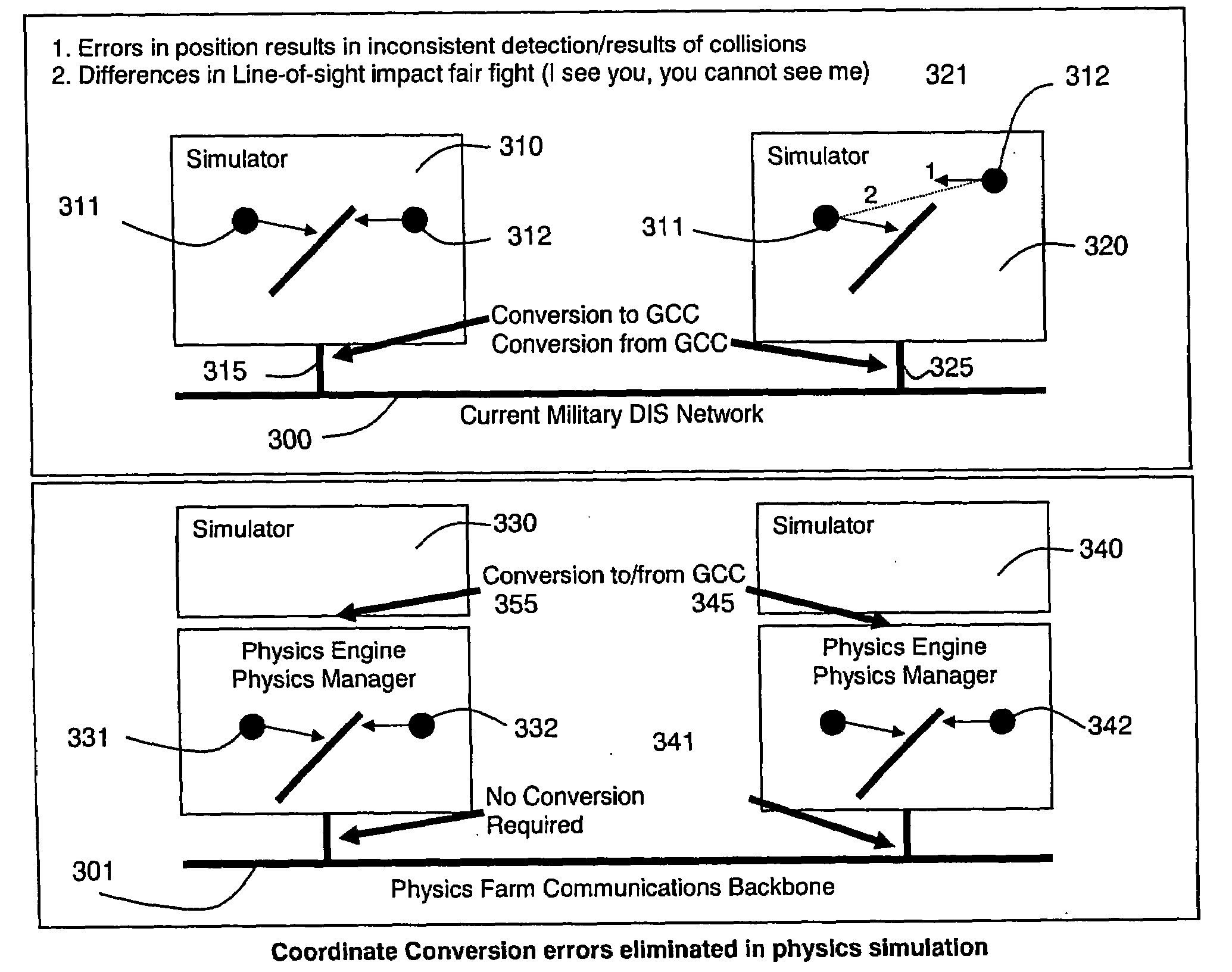
[0011]Furthermore, especially in military simulation-based training, discrepancies between various users' views of the simulated world can compromise principles of training, notably “fair fight” requirements. “Fair Fight” is a term that means no combatant has an unfair advantage over another due to differences in each participant's representation of the world. Differences in the viewed scenery of the participants can afford such an advantage to one user or another.
[0012]In addition, simulators for vehicles, especially aircraft, are usually modeled to run scripts when certain events occur to the user's ownship, such as when damage is done to the vehicle in combat. As an example, in a helicopter simulation, if a blade of the helicopter is shot at and it breaks off, the simulator normally initiates a damaged-vehicle script that is usually limited to a single type of damage scenario, and does not provide the realism of allowing a wide variety of effects for the various types of damage that may be done to the aircraft. These limitations reduce realism and also lessen to a degree the training value of the simulation.

Problems solved by technology

In using such a system, assurance that each simulator receives and responds to all PDUs from all other simulators is extremely difficult, if not impossible, as the number of simulators and simulated entities increases due to the avalanche of communication / network traffic that results from dynamically moving entities continually updating their state.
Human-In-Loop (HIL) entities tend to complicate matters even further given their interactive and inherently unpredictable behavior.
A primary problem encountered in such distributed systems is that of latency, meaning communications delay between the transmission from a remote site of data affecting the scene and the reception and display of that data at a user's station.
The consequence of latency in multi-user situations is that the actions of a remote user do not affect the scene viewed by the local user immediately, and this can result in inconsistencies in the views seen by the users in the distributed system.
Linear projections of this type do not accurately extrapolate the real position of objects under a number of circumstances, and in addition to the positional errors associated with a pure linear projection of the location of the object, it is also possible that behavior of the object will be unrealistic if it is projected to a point that it could not reach in reality, such as, for example, when the position of a moving person or vehicle is extrapolated to the other side of a solid wall, making it appear that the person or vehicle actually went through the wall.
Furthermore, especially in military simulation-based training, discrepancies between various users' views of the simulated world can compromise principles of training, notably “fair fight” requirements.
As an example, in a helicopter simulation, if a blade of the helicopter is shot at and it breaks off, the simulator normally initiates a damaged-vehicle script that is usually limited to a single type of damage scenario, and does not provide the realism of allowing a wide variety of effects for the various types of damage that may be done to the aircraft.
These limitations reduce realism and also lessen to a degree the training value of the simulation.

Method used


Image

  • Distributed Physics Based Training System and Methods
  • Distributed Physics Based Training System and Methods
  • Distributed Physics Based Training System and Methods

Examples


example

[0179]FIG. 22 is a simplified block diagram of a demonstrator used to prove the feasibility of applying physics-based modeling for applications that currently rely only on kinematics modeling. Additionally, physics-based modeling was used to incorporate dynamic “cultural features,” which, if provided for at all, have typically been modeled statically.

[0180]The demonstrator provided higher fidelity models, increased quantities of vehicles and new dynamic cultural features. In addition to the inclusion of vehicle models, dynamic cultural features were incorporated into the simulation by loading cultural feature models into the physics engine. This allowed for interactions between the cultural features and vehicles in the simulation. For example, using the physics-based approach, a vehicle was now able to push a barrel out of the way, with both the barrel and the vehicle responding in a realistic manner to the forces generated by the interaction.

[0181]The key components in the example ...


PUM


Abstract

A distributed simulation system is composed of simulator stations linked over a network that each renders real-time video imagery for its user from scene data stored in its data storage. The simulation stations are each connected with a physics farm that manages the virtual objects in the shared virtual environment based on their physical attribute data using physics engines, including an engine at each simulation station. The physics engines of the physics farm are assigned virtual objects so as to reduce the effects of latency, to ensure fair fight requirements of the system, and, where the simulation is of a vehicle, to accurately model the ownship of the user at the station. A synchronizer system is also provided that allows for action of simulated entities relying on localized closed loop controls to cause the entities to meet specific goal points at specified system time points.

Description

RELATED APPLICATIONS[0001]This application claims the priority of U.S. provisional application Ser. No. 60 / 740,579 filed Nov. 28, 2005, which is herein incorporated by reference in its entirety.FIELD OF THE INVENTION[0002]This invention relates to the field of simulators, and more particularly to the field of simulator systems for multiple users for training in military exercises or military vehicle operations, especially such systems for users that are geographically distributed relative to each other and connected by communications links such as a network or the Internet.BACKGROUND OF THE INVENTION[0003]It is known in the prior art to provide simulation systems for users distributed geographically relative to each other, potentially thousands of miles apart, with communications between the various users being transmitted over a network, such as the Internet. In these systems, each user normally has a simulation station where the user can see on a screen, a head-mounted display, or...

Claims


Application Information

Patent Timeline
Patent Type & Authority Applications(United States)
IPC IPC(8): G06G7/70
CPCH04L67/38G09B9/00H04L67/131
Inventor FALASH, MARKPOLLAK, EYTANCHEN, YUSHANWILLIAMS, JON
Owner CAE USA INC
Learn More