Laser marker

a laser marker and laser technology, applied in the field of laser markers, can solve the problems of deteriorating the position accuracy of the brightline projected to the surface to be projected, and achieve the effect of reducing the cost of the laser marker and not reducing the dynamic sensitivity of the gimbal mechanism

Inactive Publication Date: 2009-04-23
AUDIO-TECHNICA
View PDF12 Cites 10 Cited by
  • Summary
  • Abstract
  • Description
  • Claims
  • Application Information

AI Technical Summary

Benefits of technology

[0020]The rocking body rocks by relative rotation between the spherical body and a pair of shafts or by relative rotation between the spherical body and the rocking body. Even if the mutual center axes of a pair of shafts deviate from each other, there will be no variation in the contacting form or the contacting conditions betwee

Problems solved by technology

This is because if the gimbal mechanism has a mechanical resistance, the light source unit holder 80 cannot take a predetermined ideal rest position

Method used


Image

  • Laser marker
  • Laser marker
  • Laser marker

Examples


Embodiment Construction

[0026]Hereinafter, an embodiment of a laser marker according to the present invention will be described using accompanying drawings.

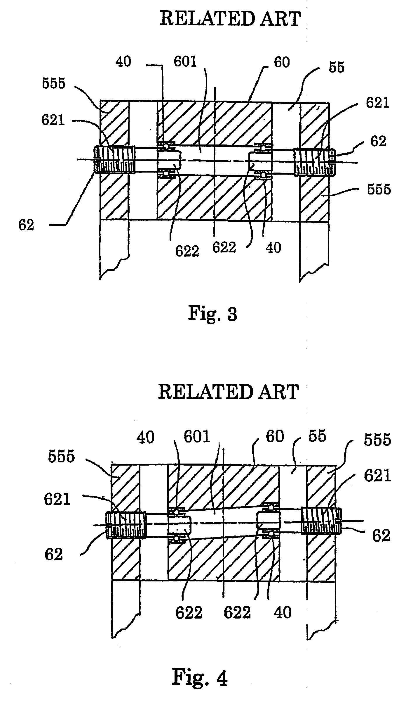
[0027]The laser marker according to the present invention is characterized in a gimbal mechanism that rockably supports a light source unit holder. The structure of the laser marker to which this gimbal mechanism is applied is not limited to the specific one, and can be applied also to a laser marker as shown in FIG. 5. Accordingly, the portion of the gimbal mechanism is described intensively, and the description of the generic configuration as the laser marker is omitted or simplified.

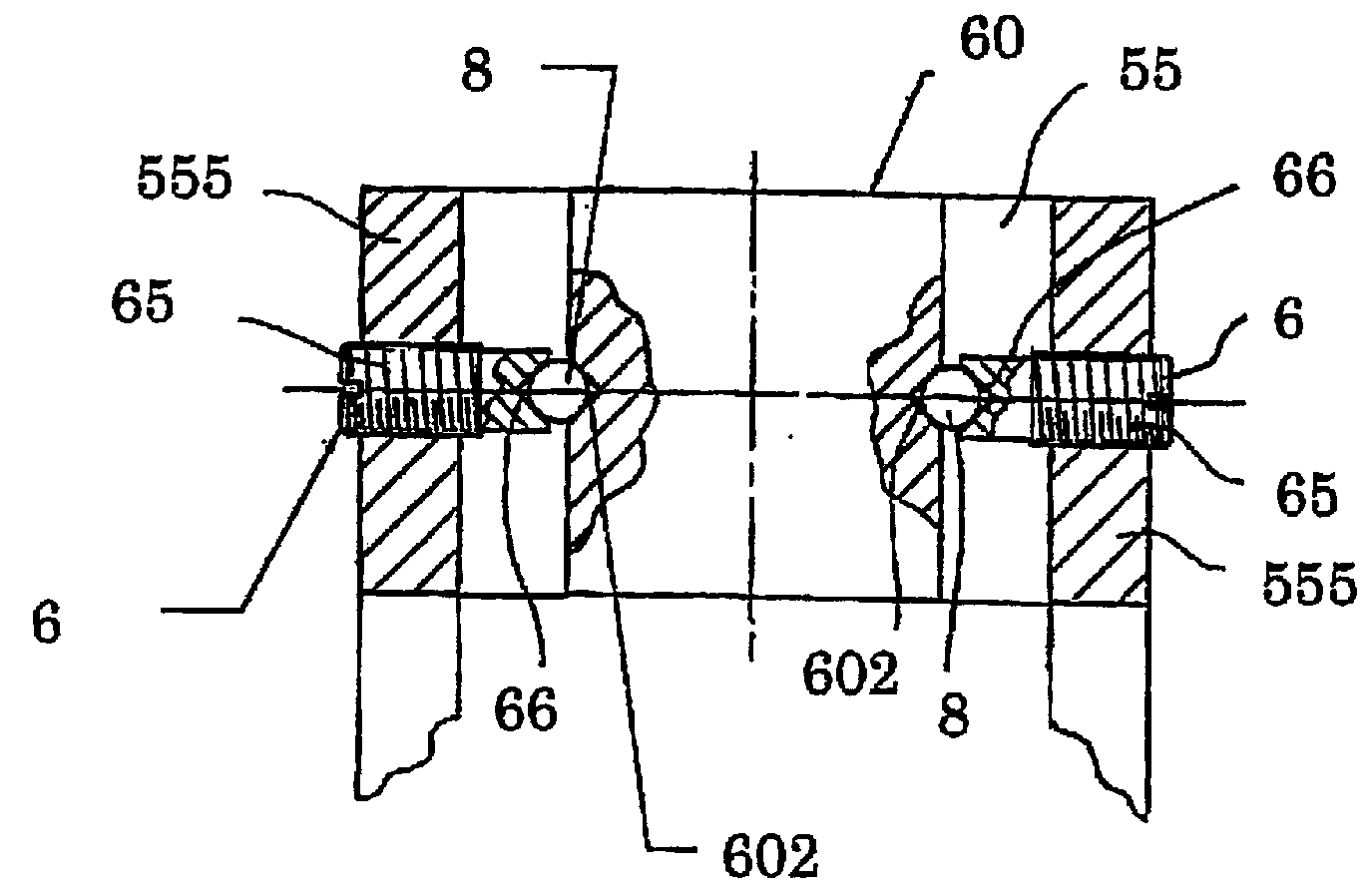
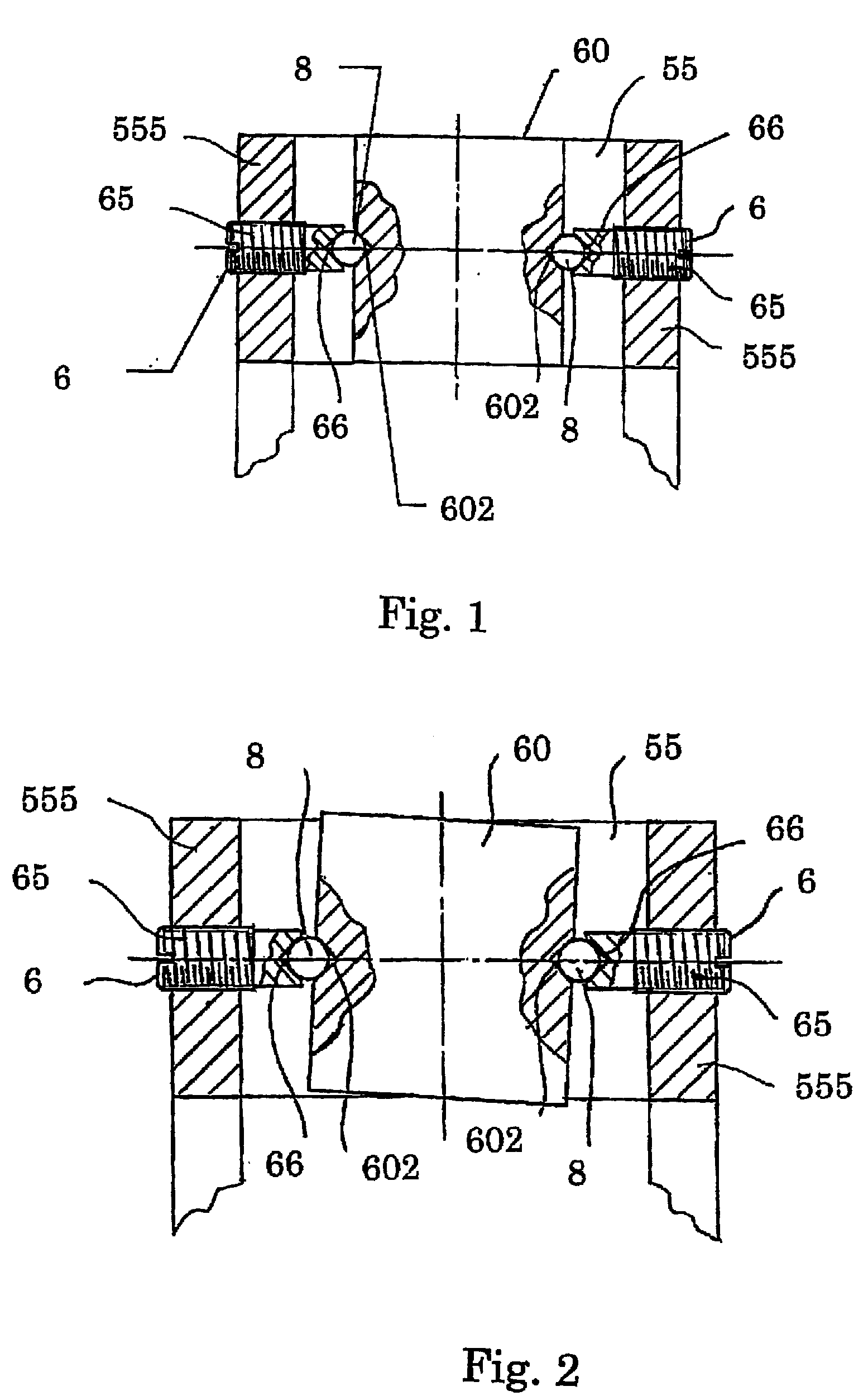
[0028]In FIG. 1, in the mutually opposing walls 555 of the gimbal frame 55, there is formed a female screw that horizontally passes through each of the walls, and a thread part 65 of the shaft 6 is screwed into the female screw. A conical shaped depression is formed at a tip of each shaft 6. This depression serves as a spherical-body receiving hole 66 that receives a part...


PUM


Abstract

A light source unit holder, on which a light source unit is mounted, is rockably supported via a gimbal mechanism, and projects a brightline using a laser beam emitted from the light source unit, the gimbal mechanism includes a pair of shafts that support the rocking body rockably from both sides thereof, a spherical-body receiving hole is formed at a tip of the pair of shafts, and also in the rocking body a spherical-body receiving hole is formed in a position to which the tips of the pair of shafts face, and a spherical body is interposed between the spherical-body receiving hole of the pair of shafts and the spherical-body receiving hole of the rocking body, the latter spherical-body receiving hole facing the spherical-body receiving hole of each shaft, so that the rocking body is rockably supported, for preventing dynamic sensitivity of the gimbal mechanism from decreasing.

Description

BACKGROUND OF THE INVENTION[0001]1. Field of the Invention[0002]The present invention relates to a laser marker that projects a marking laser line light (hereinafter, referred to as a “brightline”) to a surface to be projected, such as a wall, a ceiling, or a floor, in a construction site or the like. In particular, the present invention relates to a structure of a supporting member that rockably supports a light source unit holder of the laser marker.[0003]2. Related Background of the Invention[0004]The laser marker converts divergent light, which is emitted from a laser light source such as a semiconductor laser, into a parallel beam by means of a collimate lens, and then transmits this beam through a cylindrical rod lens and thereby diffuses this only in one direction and projects this diffusion light to a surface to be projected, such as a wall, a ceiling, and a floor. The laser beam projected onto the surface to be projected serves as a vertical brightline or a horizontal brigh...

Claims


Application Information

Patent Timeline
IPC IPC(8): G01C15/02
CPCG01C15/004
Inventor TAMAMURA, AKIHITO
Owner AUDIO-TECHNICA
Why Eureka
Try Eureka