Supercharge Your Innovation With Domain-Expert AI Agents!

Pressure application driving unit of welding gun

a driving unit and pressure technology, applied in the direction of resistance electrode holders, manufacturing tools, manufacturing tools, etc., can solve the problems of high manufacturing cost, inability to use the hollow rotary shaft of the ordinary motor, and inability to implement with ease, so as to achieve the effect of low manufacturing cost and ease of implementation

Inactive Publication Date: 2009-04-23
OBARA CORP
View PDF4 Cites 0 Cited by
  • Summary
  • Abstract
  • Description
  • Claims
  • Application Information

AI Technical Summary

Benefits of technology

The invention is a pressure application driving unit for a welding gun. It aims to solve the problems of conventional units by being safe, low in cost, and compact. The unit uses a hollow rotary shaft of the motor and a screw shaft to drive the pressure application shaft. A screw shaft fixing member is fixed to the end face of the rotary shaft to secure the screw shaft. The invention provides a space in the hollow through hole of the motor's rotary shaft to house the nut and screw, which are then threaded together. This design reduces the length of the pressure application driving unit and allows for the use of a common motor for both rotating the nut and screw shaft, saving manufacturing costs. The integrated screw shaft and screw shaft fixing member make it easy to align and assemble the components. Overall, the invention provides a compact, safe, and cost-effective pressure application driving unit for welding guns.

Problems solved by technology

Accordingly, the hollow rotary shaft of the ordinary motor can not be used as it is, and it is necessary for the rotary shaft to be subjected to special machining, which is not implemented with ease.
Further, in the case of the foregoing second conventional pressure application driving unit of the welding gun, the pressure application shaft forms the screw shaft, there is a likelihood that welding sputter adheres to the screw shaft when applying the pressure, causing a problem that a protection means of the screw shaft is required and a rotation stop mechanism of the screw shaft is not easy.

Method used


Image

  • Pressure application driving unit of welding gun
  • Pressure application driving unit of welding gun
  • Pressure application driving unit of welding gun

Examples


first embodiment

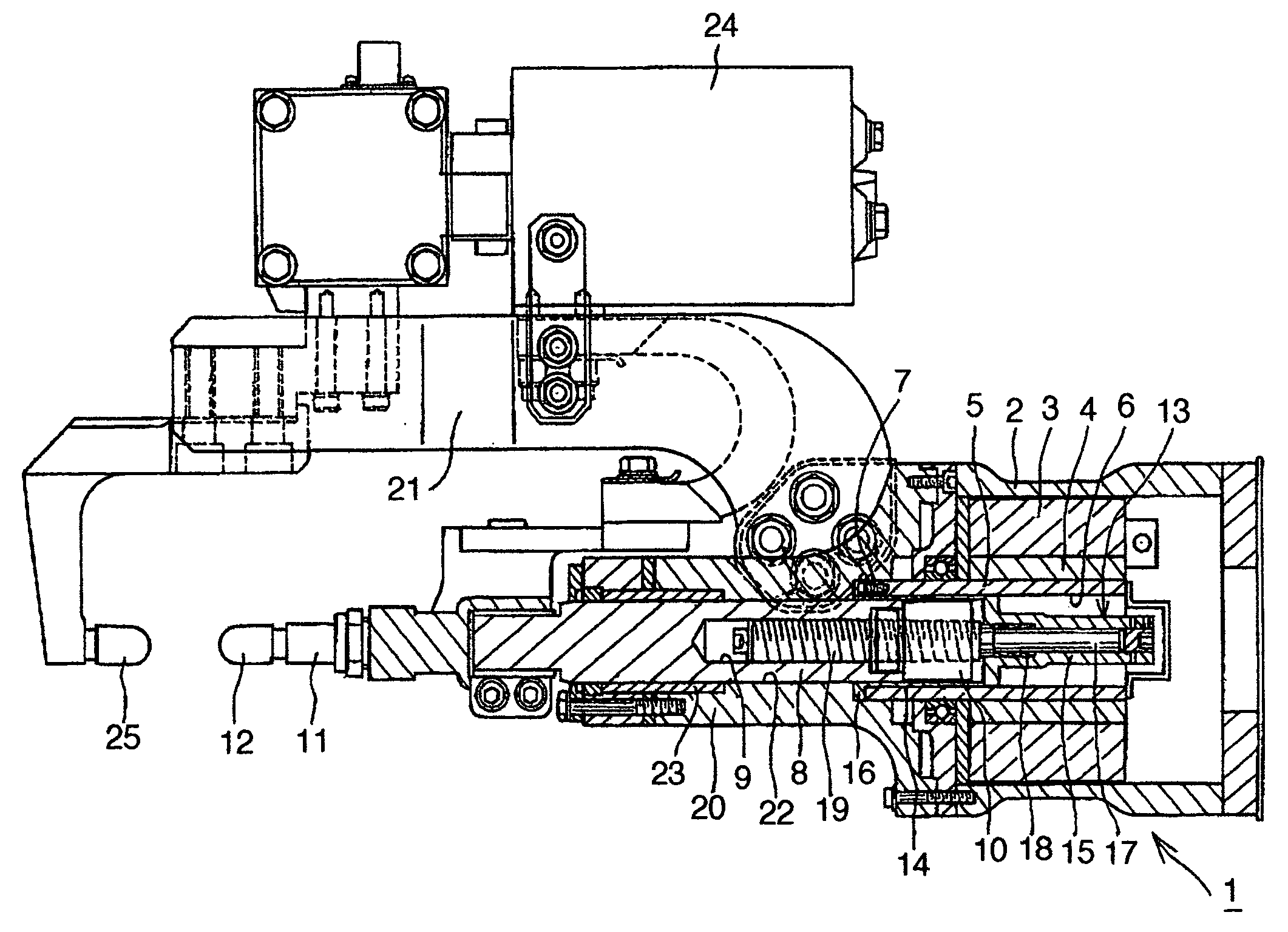
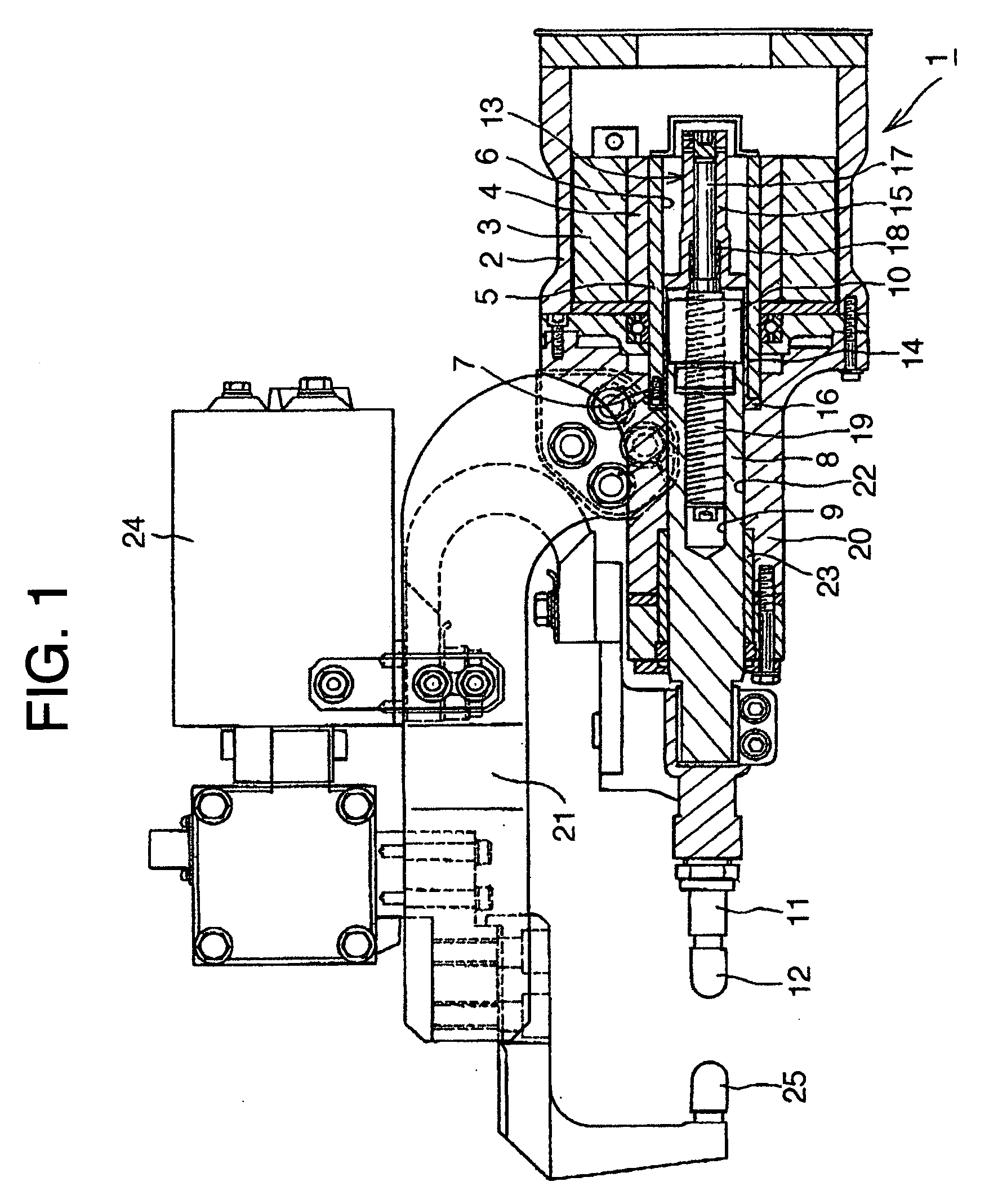
[0016]Described now with reference to FIG. 1 is the first embodiment of the invention.

[0017]In FIG. 1, depicted by 1 is a servomotor which comprises a stator winding 3 fixed to an outer shell 2 of the servomotor 1, a rotor magnetic pole 4 disposed at an inner periphery of the stator winding 3 and a rotary shaft 5 to which the rotor magnetic pole 4 is fixed, and a hollow through hole 6 is formed in the rotary shaft 5. A plurality of tap holes are formed on the front end face of the rotary shaft 5.

[0018]Depicted by 8 is a pressure application shaft and it has a hole 9 at the center portion thereof in the axial direction thereof in which the tip end side of a screw shaft, described later, is housed, a nut 10 fixed to and arranged at the rear end side thereof which is disposed integrally with the pressure application shaft 8 which is nonrotable, and an electrode 12 attached to the tip end side thereof via a tip holder 11. The nut 10 may be formed by integration molding at the rear end s...

second embodiment

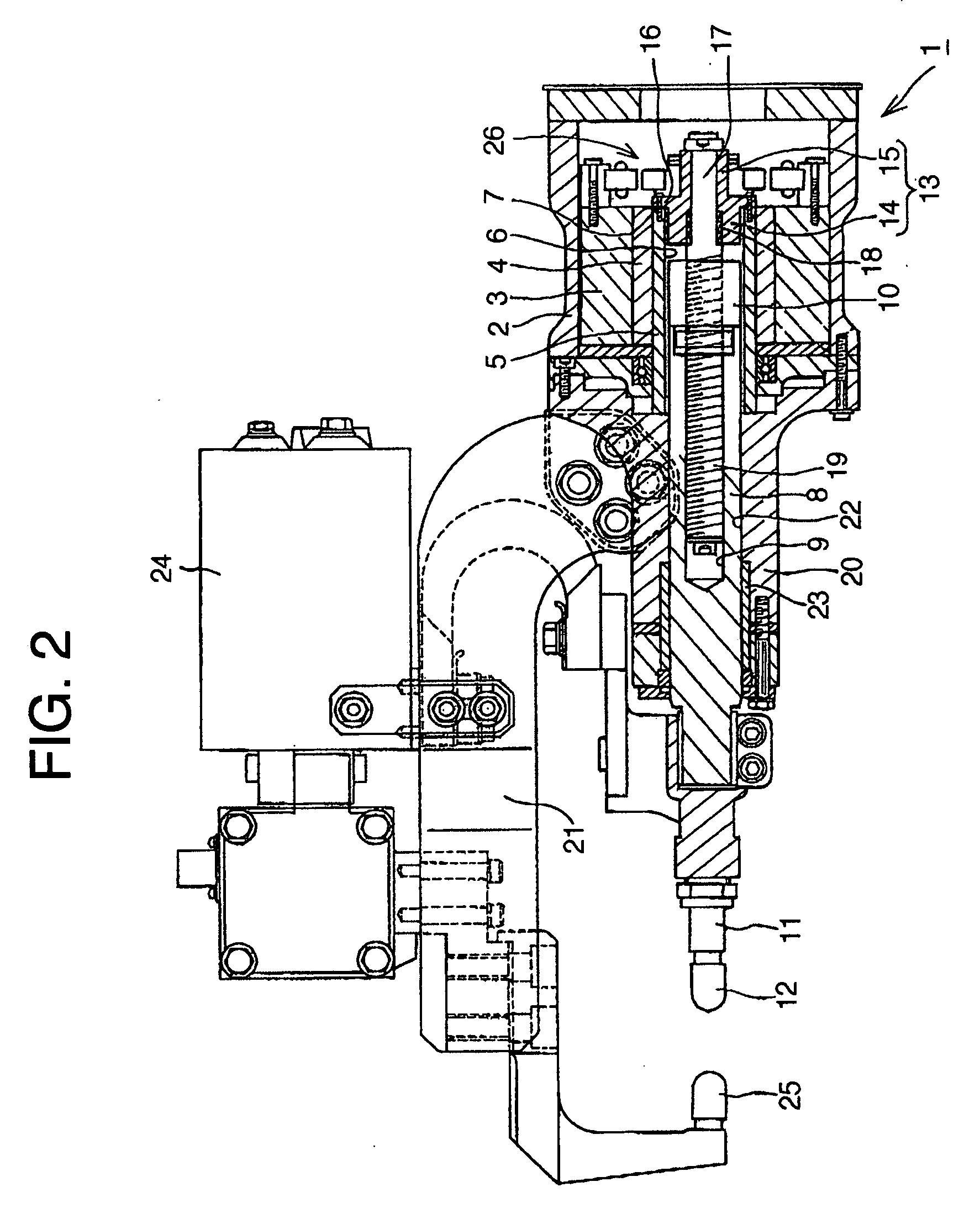
[0024]Described now with reference to FIGS. 2 and 3 is the second embodiment of the invention.

[0025]According to the second embodiment, the screw shaft fixing member 13 of the first embodiment is fixed to a plurality of tap holes formed on the rear end face of a rotary shaft 5. Components of the second embodiments are substantially the same as those of the first embodiment except the configuration mentioned immediately above, and hence the explanation thereof is omitted.

[0026]A member attached to a later half of a screw shaft fixing member 13 and depicted by 26 is a position detection member.

[0027]Even in the second embodiment, it is possible to expect substantially the same effect as the first embodiment.

[0028]Further, as shown in FIG. 3, in the case where the screw shaft fixing member 13 and a screw shaft 17 are preliminarily integrated with each other by welding or retainment by rotation stop, and so force, and the integrated screw shaft fixing member 13 and screw shaft 17 is fix...


PUM

PropertyMeasurementUnit
pressureaaaaaaaaaa
diameteraaaaaaaaaa

Abstract

The invention provides a pressure application driving unit of a welding gun that is safe, low in manufacturing cost, and compact as a whole by employing a hollow rotary shaft of the ordinary motor as it is and fixing a screw shaft fixing member to an end face of the rotary shaft, thereby reciprocating a pressure application shaft by the rotation of a screw shaft. The pressure application driving unit of a welding gun comprises a hollow through hole formed in a rotary shaft of a motor, a pressure application shaft having a portion pulled in the hollow through hole of the motor via a screw shaft to be driven by the motor, a hole for housing a tip end side of the screw shaft formed on the center portion of the pressure application shaft in the axial direction of the pressure application shaft, a nut at the end side of the pressure application shaft and a screw of the screw shaft are threaded with each other, the pressure application shaft side being nonrotatable, and a space formed in the hollow through hole and capable of housing the nut that is threaded with the screw shaft, wherein a screw shaft fixing member is fixed to tap holes formed on an end face of the rotary shaft of the motor and the screw shaft is fixed in the screw shaft fixing member.

Description

FIELD OF THE INVENTION[0001]The invention relates to a pressure application driving unit of a welding gun comprising a hollow through hole formed in a rotary shaft of a motor, a pressure application shaft having a portion pulled in the hollow through hole of the motor via a screw shaft to be driven by the motor, a hole for housing a tip end side of the screw shaft formed on the center portion of the pressure application shaft in the axial direction of the pressure application shaft, a nut at the end side of the pressure application shaft and a screw of the screw shaft are threaded with each other, the pressure application shaft side being nonrotatable, a space formed in the hollow through hole and capable of housing the nut to be threaded with the screw shaft.[0002]There has been conventionally known a pressure application driving unit of a welding gun comprising a hollow through hole formed in a rotary shaft of a motor, a pressure application shaft having a portion pulled in the ho...

Claims


Application Information

Patent Timeline
Patent Type & Authority Applications(United States)
IPC IPC(8): B23K11/31
CPCY10T74/18656B23K11/315
Inventor SATO, YOSHIO
Owner OBARA CORP
Features
  • R&D
  • Intellectual Property
  • Life Sciences
  • Materials
  • Tech Scout
  • Unparalleled Data Quality
  • Higher Quality Content
  • 60% Fewer Hallucinations
Learn More