
Intake pipe of internal combustion engine

Active Publication Date: 2009-04-23
TOYOTA JIDOSHA KK
View PDF3 Cites 2 Cited by
  • Summary
  • Abstract
  • Description
  • Claims
  • Application Information

AI Technical Summary

Benefits of technology

[0004]An object of the present invention is to overcome the problem above, and provide an intake pipe of an internal combustion engine, the intake pipe providing sufficient improvement in intake efficiency.

Problems solved by technology

However, if the air does not flow smoothly when it moves around an end portion of a partition wall that allows the upper and lower surge tanks to be apart, improvement in intake efficiency of the engine may be hindered.

Method used


Image

  • Intake pipe of internal combustion engine
  • Intake pipe of internal combustion engine
  • Intake pipe of internal combustion engine

Examples


Embodiment Construction

[0026]An embodiment of the present invention will be described with reference to the drawings. In the drawings to be referred to below, the same or corresponding members are denoted by the same numbers.

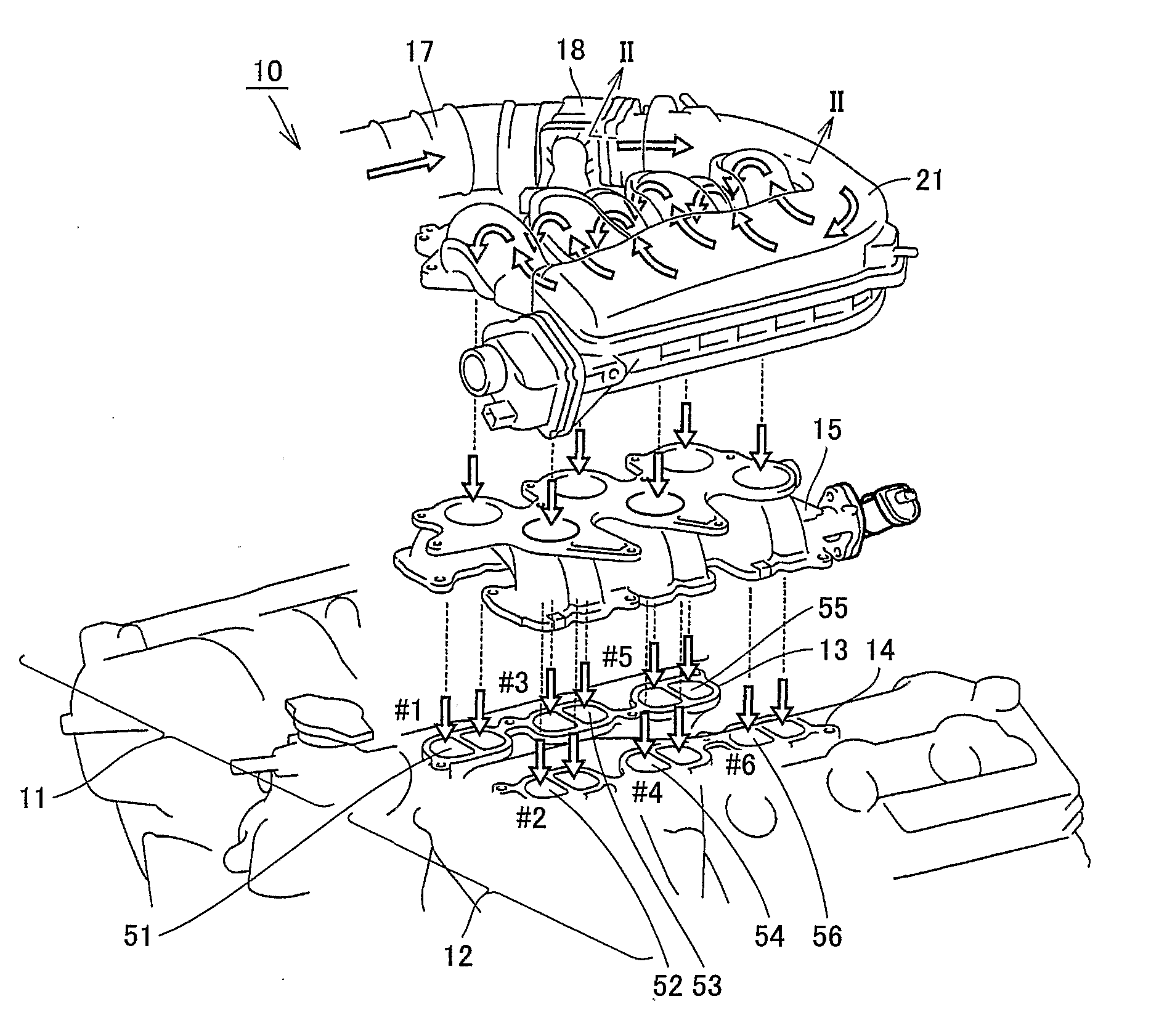
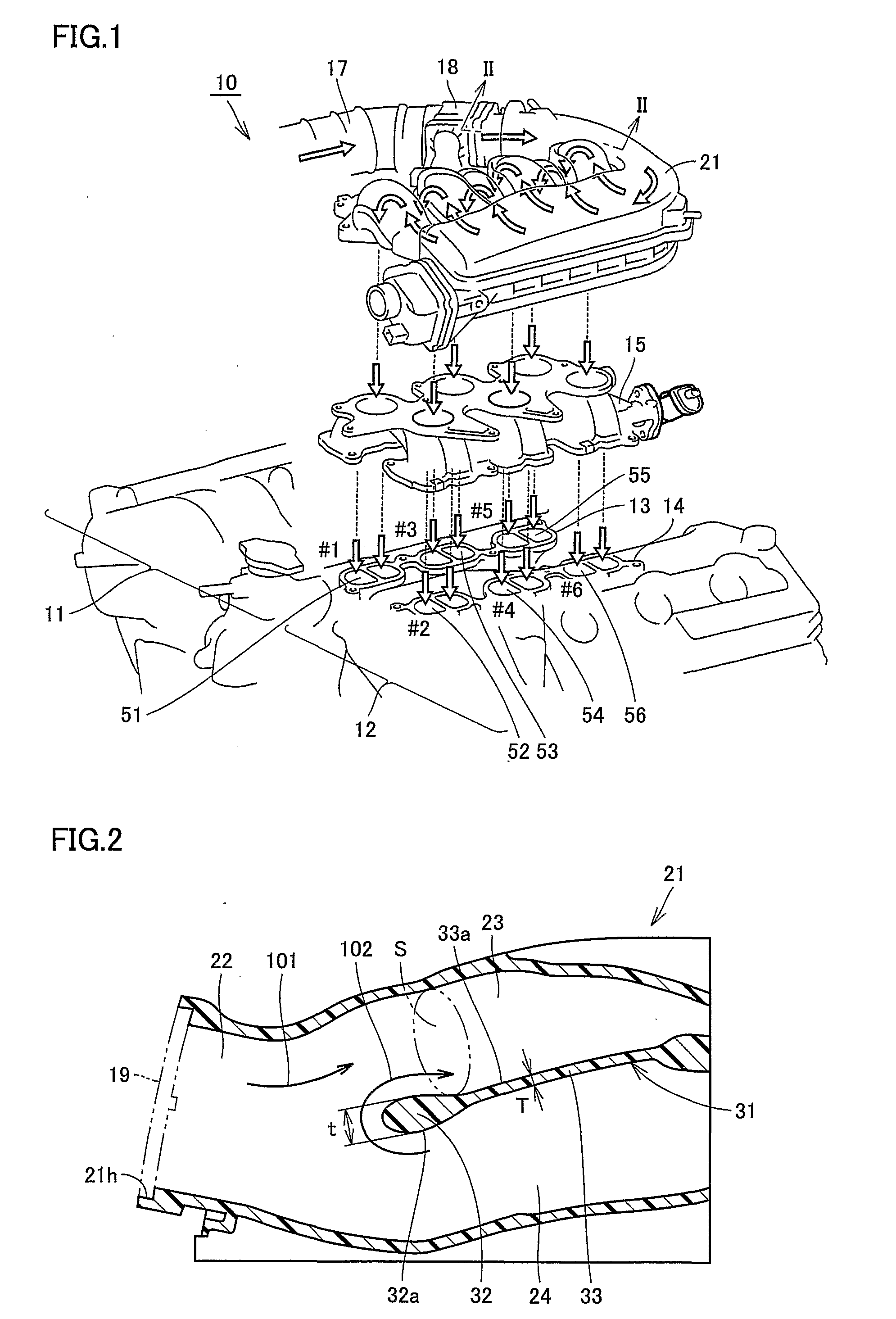
[0027]FIG. 1 is an exploded view showing an engine to which an intake pipe according to the embodiment of the present invention is applied. Referring to FIG. 1, an intake pipe according to the present embodiment is applied to a vehicle gasoline engine 10, which is a V-type six-cylinder engine (hereinafter referred to as engine 10). Engine 10 includes a right bank 11 and a left bank 12 arranged in a V-shape.

[0028]Cylinders denoted by numbers #1, #3 and #5, respectively (hereinafter referred to as #1 cylinder, #3 cylinder, and #5 cylinder), are formed at right bank 11 in a row in this order from the front side to the rear side of the vehicle. Cylinders denoted by numbers #2, #4 and #6, respectively (hereinafter referred to as #2 cylinder, #4 cylinder, and #6 cylinder), are formed at lef...


PUM

PropertyMeasurementUnit
Thicknessaaaaaaaaaa
Efficiencyaaaaaaaaaa

Abstract

An intake pipe of an internal combustion engine includes a main flow passage allowing air introduced into the engine to flow therethrough, an upper branch flow passage branching off from the main flow passage and communicating with #2 cylinder, #4 cylinder, and #6 cylinder, a lower branch flow passage branching off from the main flow passage sand communicating with #1 cylinder, #3 cylinder, and #5 cylinder, and a partition wall allowing the upper branch flow passage and the lower branch flow passage to be apart. The partition wall has an end portion that faces the main flow passage. The end portion is formed of a spherical surface. With such a configuration, the intake pipe of the internal combustion engine, which intake pipe provides sufficient improvement in intake efficiency, is provided.

Description

TECHNICAL FIELD[0001]The present invention relates to an intake pipe of an internal combustion engine, and more particularly to an intake pipe of an internal combustion engine, which intake pipe is applied to a V-type six-cylinder engine.BACKGROUND ART[0002]As to a conventional intake pipe of an internal combustion engine, Japanese Patent Laying-Open No. 7-19132, for example, discloses an intake device for a V-type engine intended for changing the direction of an opening by reducing a protrusion amount of an upper stream side intake channel above the engine and by avoiding interference with a cylinder head cover. In this document, the intake device is mounted on a transversely-installed V-type six-cylinder engine where a front bank and a rear bank are installed in a V-shape, each of the front bank and the rear bank being formed of a cylinder group including cylinders whose intake strokes do not occur successively. The intake device has a surge tank having a two-tiered structure. At ...

Claims


Application Information

Patent Timeline
IPC IPC(8): F02M35/116
CPCF02M35/10045F02M35/10262F02M35/10321F02M35/10327Y02T10/14F02M35/10354F02M35/116Y02T10/146F02M35/10347Y02T10/12
Inventor MIYAJI, YOSHIHIRO
Owner TOYOTA JIDOSHA KK
Learn More