Steel ball surface development device and method

A technology of steel balls and accommodating grooves, which is used in measuring devices, material analysis by optical means, instruments, etc., can solve the problems of high false detection rate and insufficient rolling and unfolding of steel balls.

Active Publication Date: 2015-01-07
NINGBO MINGKE MOLD
View PDF10 Cites 1 Cited by
  • Summary
  • Abstract
  • Description
  • Claims
  • Application Information

AI Technical Summary

Problems solved by technology

[0004] Aiming at the deficiencies in the above-mentioned prior art, the object of the present invention is to provide a steel ball surface unfolding device and method. The device utilizes the steel ball's own gravity to drive the steel ball to roll and unfold in one direction, and at the same time drives the steel ball to roll in one direction by means of a roller bar. Rolling and unfolding in another direction, which solves the technical problem of high false detection rate caused by the inability of steel balls to fully roll and unfold in the prior art

Method used


Image

  • Steel ball surface development device and method
  • Steel ball surface development device and method
  • Steel ball surface development device and method

Examples


Embodiment 1

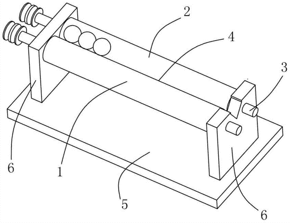
[0031] Example 1, see figure 1 Shown:

[0032] This embodiment comprises two roller bars 1, and these two roller bars 1 include rotating shaft 3 and rolling sleeve 2, and rolling sleeve 2 is elongated cylindrical shape, and its material is plexiglass, and rolling sleeve 2 is set on rotating shaft 3, steel The contact between the ball and the roller sleeve 2 made of plexiglass can prevent the steel ball from being scratched or bumped, and can also reduce the rolling friction of the steel ball on the roller sleeve 2 . The two rollers are rotatably erected on two opposite supporting plates 6 , the roller sleeve 2 is located between the two supporting plates 6 , and the two supporting plates 6 are fixedly arranged on the base 5 .

[0033] The two roller bars 1 are arranged side by side in parallel, and there is a gap between the two roller bars 1 to avoid mutual friction when the roller bars 1 rotate, and an accommodating groove 4 for carrying steel balls is formed between the tw...

Embodiment 2

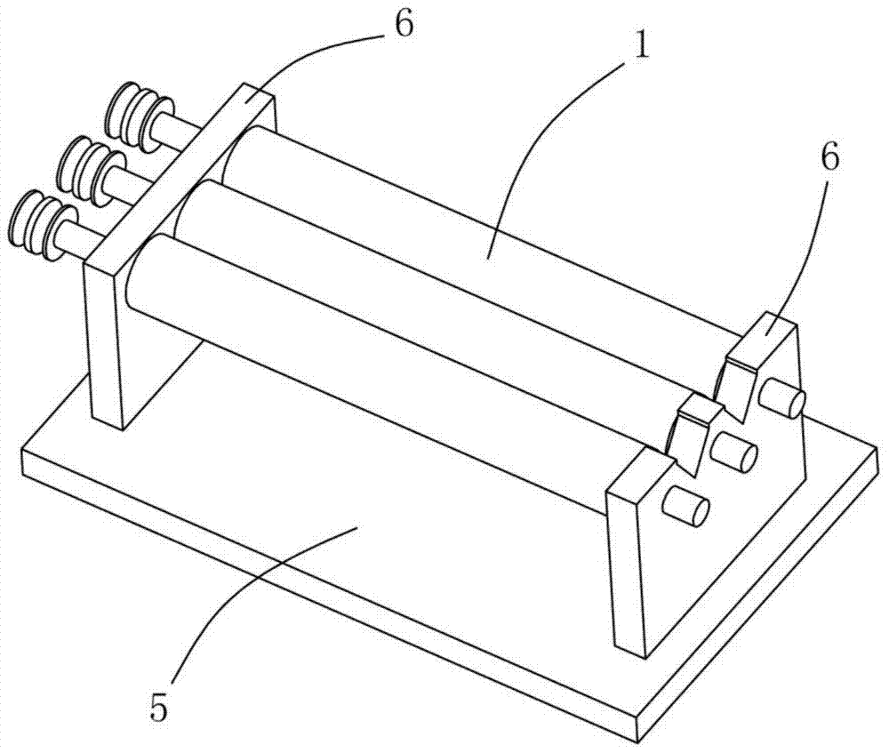
[0037] Example 2, see figure 2 and image 3 Shown:

[0038] The difference between this embodiment and Embodiment 1 is that this steel ball surface unfolding device includes three roller bars 1, the three roller bars 1 are arranged side by side, and two accommodating grooves 4 are formed, and the three roller bars 1 are in the same direction. synchronous rotation.

[0039] When the camera is used to capture the surface image of the steel ball, the camera is set above the roller bar 1, and the visual recognition area of ​​the camera only needs to cover the area where more than three continuous steel balls in the accommodating tank 4 are located. Usually the viewfinder range of the camera is circular or rectangular, and the steel balls in the accommodating groove 4 are arranged in a straight line, so there are still a large number of unused areas in the viewfinder range of the camera. In this embodiment, three rolling bars 1 The main purpose of setting side by side is to mak...

Embodiment 3

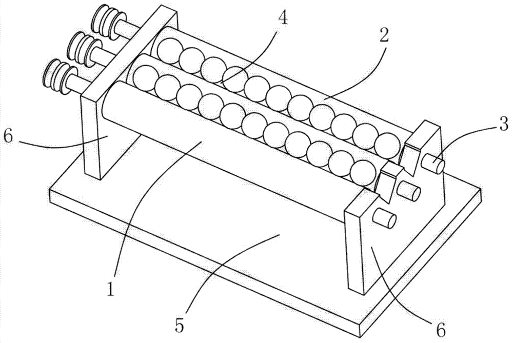
[0042] Example 3, see Figure 4 and Figure 5 Shown:

[0043] In this embodiment, a steel ball surface unfolding device with three roller bars 1 arranged side by side is used as an example for illustration. It is fixed on two support plates 6 by screws. The block 7 is provided with a limit stop groove 8 corresponding to the accommodation groove 4, and the limit stop groove 8 acts as a limit stop to the steel ball in the accommodation groove 4, preventing the steel ball from moving from the accommodation groove 4. Roll out on both sides.

[0044] The limit stop groove 8 is a vertical through groove structure, and the limit stop groove 8 is located directly above the accommodating groove 4 , and the camera captures the image of the upper surface of the steel ball in the accommodating groove 4 through the limit stop groove 8 .

[0045] The stop block 7 is made of light-colored plexiglass, and a number of soft light beads 9 are installed along the groove wall of the limit stop...


PUM


Abstract

The invention discloses a steel ball surface development device and method. The steel ball surface development device comprises at least two rolling bars, an accommodating groove for supporting a steel ball is formed between the two adjacent rolling bars, the steel ball can roll from one end of the accommodating groove to the other end under the action of self-gravity, and at least one of the two adjacent rolling bars can be used for driving the steel ball so that the steel ball and the rolling bar synchronously roll in the accommodating groove. The device can utilizes self-gravity of the steel ball to drive the steel ball to carry out rolling development along one direction and simultaneously utilize the rolling bars to drive the steel ball to carry out rolling development along the other direction so that the problem that the prior art does not realize complete rolling development thereby producing a high false detecting rate is solved. The method can form a complete steel ball surface image by reduction of shooting frequency thereby improving steel ball surface image taking efficiency, and has small taken image overlapping regions thereby reducing image processing redundancy data and shortening steel ball surface defect identification processing time.

Description

technical field [0001] The invention relates to the technical field of steel ball sorting equipment based on machine vision, in particular to a steel ball surface unfolding device of the sorting equipment which adopts a camera to acquire steel ball surface images. Background technique [0002] Machine vision is to use machines instead of human eyes for measurement and judgment. Machine vision technology refers to converting the captured target into an image signal through machine vision products (ie, image capture device, which is divided into CMOS and CCD) and transmitting it to a dedicated image. The processing system converts the information into digital signals according to pixel distribution, brightness, color and other information; the image system performs various calculations on these signals to extract the characteristics of the target, and then controls the on-site equipment actions according to the results of the discrimination. [0003] The surface defect detecti...

Claims


Application Information

Patent Timeline
Patent Type & Authority Applications(China)
IPC IPC(8): G01N21/892B07C5/342
Inventor 李方
Owner NINGBO MINGKE MOLD
Why Eureka
Try Eureka