[0030]The outline shape of loaded soil on a blade according to the present invention is a shape that greatly protrudes frontward from the top end to the lower end of said central front portion exceeding the angle of repose in the central part of the blade similar to the blade that is disclosed in WO2004 / 044337A1. On contrary to this, in the conventional blades, the outline shape of carried soil is a straight, flat shape that has an inclination angle substantially equal to the angle of repose from the top end to the lower end of the blade. That is, similarly to the foregoing WO2004 / 044337A1, in the present invention, the amount of digging and soil carrying can be also maximized with a minimum energy amount in a short time, and the fuel efficiency of a work machine is remarkably improved. As a result, it is possible to reduce cost per earthwork amount.
[0031]After the blade that is disclosed in WO2004 / 044337A1 has been proposed, various types of experimental operation are repeatedly performed, and the problems stated above are found. For this reason, various types of experimental operation and redesign are repeatedly performed. As a result, it is found that a unique and complicated blade shape according to the present invention causes that soil is less likely to remove from the surface of a blade in digging, that variation occurs in digging efficiency, and that soil drops off from the blade when soil is carried in turning operation. Specifically, examples of reasons that cause these problems are provided that the front curved surface of the blade and the rearward inclined posture of the whole blade are configured similarly to conventional, exemplary semi-U-shaped blades, and that indices are not defined to objectively determine the optimal shapes of the central front portion, the interposition front portion and the side front portion in accordance with the capacity of a blade, and the relative ratio of the blade widths of the front portions and the like.
[0032]In the present invention, the blade front surfaces of said central front portion, said interposition front portion, and said side front portion are preferably inclined rearward similarly to conventional blades. But, if the blade front surfaces are inclined rearward too much, carried soil sticks on the blade and does not slide down in soil dumping. This results from the unique blade shape according to the present invention. In order to avoid this, it is conceivable that the edge angle is designed similar to conventional blades, and the front surface of each edge section extends along the elongation line of the front surface of the blade lower end. In the case where the whole blade is inclined rearward, on condition that the inclination angle of the surface of soil that stands on and is held by a blade, i.e., the angle of repose is fixed, it is possible to reduce the ground-touch length of the soil that stands on the ground, but it is possible to load a large amount of soil on the blade. For this reason, also in the case where the front surface of each edge section is arranged on the elongation line of the front surface of each blade lower end, it is necessary to devise a method of inclining the whole curved surface of the blade rearward. If this devisal is attained, in addition to ensuring conventional digging capability, it is possible to increase the amount of carried soil and to greatly reduce soil carrying resistance and the like, and it is possible to greatly reduce consumption power per traction force, and as a result it is possible to provide excellent, low fuel consumption performance.
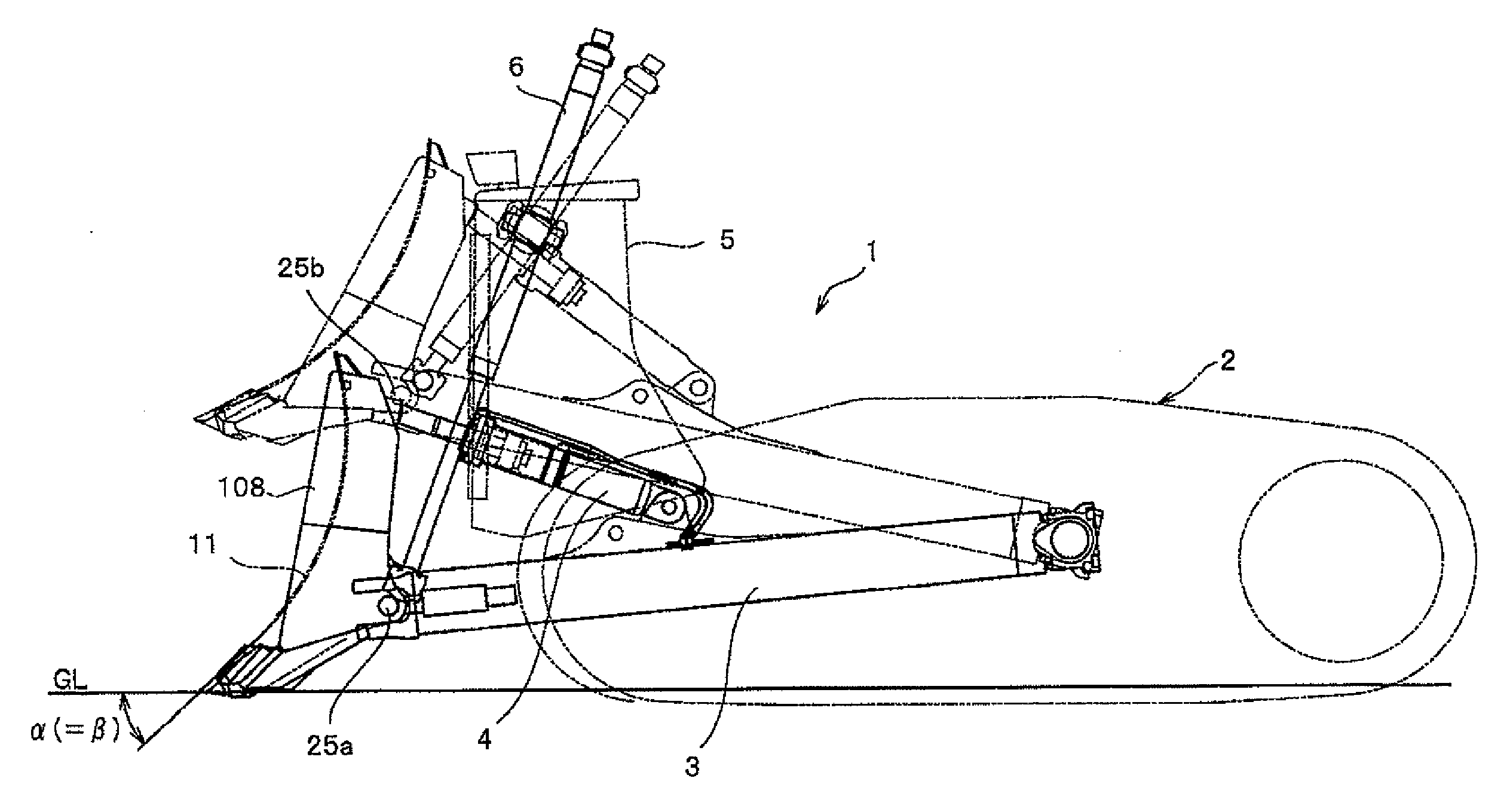
[0033]In the blade device according to the present invention that has the aforementioned unique whole shape, in the state where the edge angle α of the edge section is the same as the edge angle in the foregoing WO2004 / 044337A1, and the rearward inclination angle γ is 0°, the top end of the edge section is secured to the lower end of the front surface of the blade that is formed in an arc-shaped surface with a predetermined curvature radius in the tangential direction of said arc surface. According to the result of experiment, in the case where the edge section is secured to the lower end of the front surface of the blade that is formed in an arc-shaped surface with the same curvature radius (=0.5 to 0.7×H, where H is the height from the ground surface to the blade top end) as WO2004 / 044337A1 to extend in the tangential direction of the arc-shaped surface, the rearward inclination posture of the blade rises. As a result, the amount of soil loading decreases. For this reason, the edge angle α is designed in a range of 40° to 55° similar to WO2004 / 044337A1, which is smaller than a typical angle not less than 50° in conventional blades, in order to maintain the rearward inclination posture of the whole blade. If the edge angle α is smaller than this range, digging efficiency greatly decreases. However, it is found that, if the edge angle α is simply designed small, a force becomes weak that presses soil that already stands on the blade upward of the blade by soil that is being excavated. In particular, in digging, soil is likely to stick on the blade, and soil is less likely to remove from the blade, and as a result the resistance of soil increases. Consequently, a desired loading amount cannot be provided.
[0034]Therefore, in the present invention, in order to avoid the deterioration of digging performance, the edge angle α of the blade is designed in range of 40° to 55°, and the curvature radius of the arc-shaped surface is greatly increased relative to the radius of the aforementioned arc-shaped surface of the front surface in conventional blades with the same blade capacity. That is, typically, such a curvature radius is designed in a range of not less than 0.5 and not more than 0.7 time the blade height H that is calculated based on the blade capacity, on contrary to this, the curvature radius according to the present invention is designed in a range of not less than 0.7 and not more than 1.0 time the blade height H. In the case where the radius of the arc-shaped surface is thus increased, soil that is loaded on the blade in digging is unlikely to stick on the front surface of the blade, and the resistance of soil becomes low, and as a result soil is smoothly moved upward. Consequently, it is possible to provide a desired amount of soil carrying. Also, even in the case where the rearward inclination angle γ that is the difference between the edge angle α and the digging angle β, dissimilar to the case where digging is performed by using simple design with the digging angle β, soil removal is improved. Note that the rearward inclination angle γ preferably falls within a range of 0° to 15°.
[0035]Also, in a blade device that has the aforementioned unique blade shape according to the present invention, it is found that the digging efficiency of the blade device is determined by three parameters of the blade width W1 of the central front portion, the interval Wt (hereinafter, referred to as a recessed amount), and the bending angle δ. The interval Wt is an interval between the intersection of the edge of the interposition front portion and the edge of the side front portion, and the elongation line of the first edge of the central front portion. The bending angle δ is an angle of the edge of the second edge section of the interposition front portion that is bent rearward relative to the edge of the first edge section of the central front portion. The above equations (II) and (III) show the correlation among the three parameters. In addition, said rearward bending angle δ has the upper and lower limits. The lower limit specifies the lower limit (%) of said digging efficiency. For example, the lower limit ensures that the digging efficiency in the present invention exceeds the digging efficiency in semi-U-shaped blades. Also, the upper limit of the rearward bending angle δ ensures that carried soil is prevented from dropping off when soil is carried in turning operation.

