

Waterproof Structure and Electronic Equipment
a technology of electronic equipment and structure, applied in the direction of transducer diaphragms, electrical apparatus casings/cabinets/drawers, electromechanical transducers, etc., can solve the problems of difficult to adopt a sealed structure for the casing, difficult to meet all the conditions, and difficult to fix the panel and the casing firmly together, etc., to achieve high waterproofness, simplify the structure, and reduce the number of components
- Summary
- Abstract
- Description
- Claims
- Application Information
AI Technical Summary
Benefits of technology
Problems solved by technology
Method used
Image

Examples
first embodiment
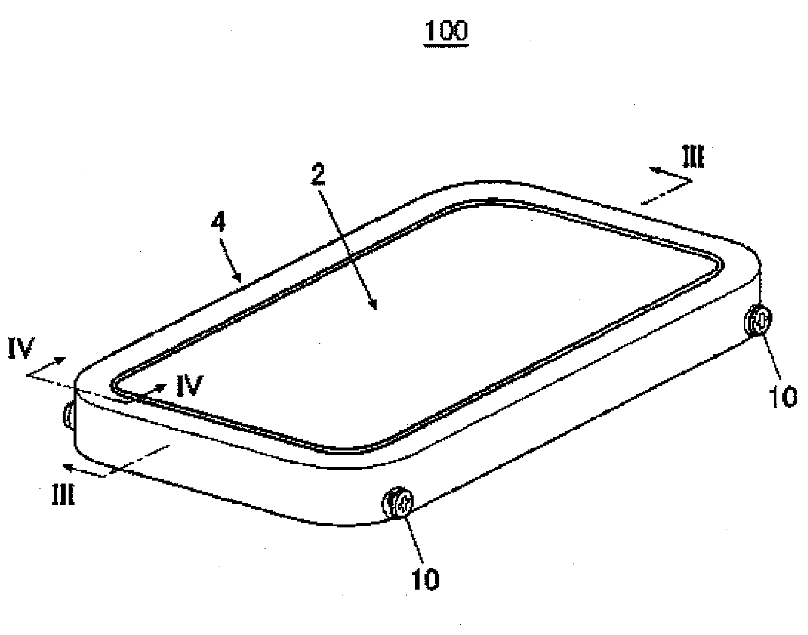
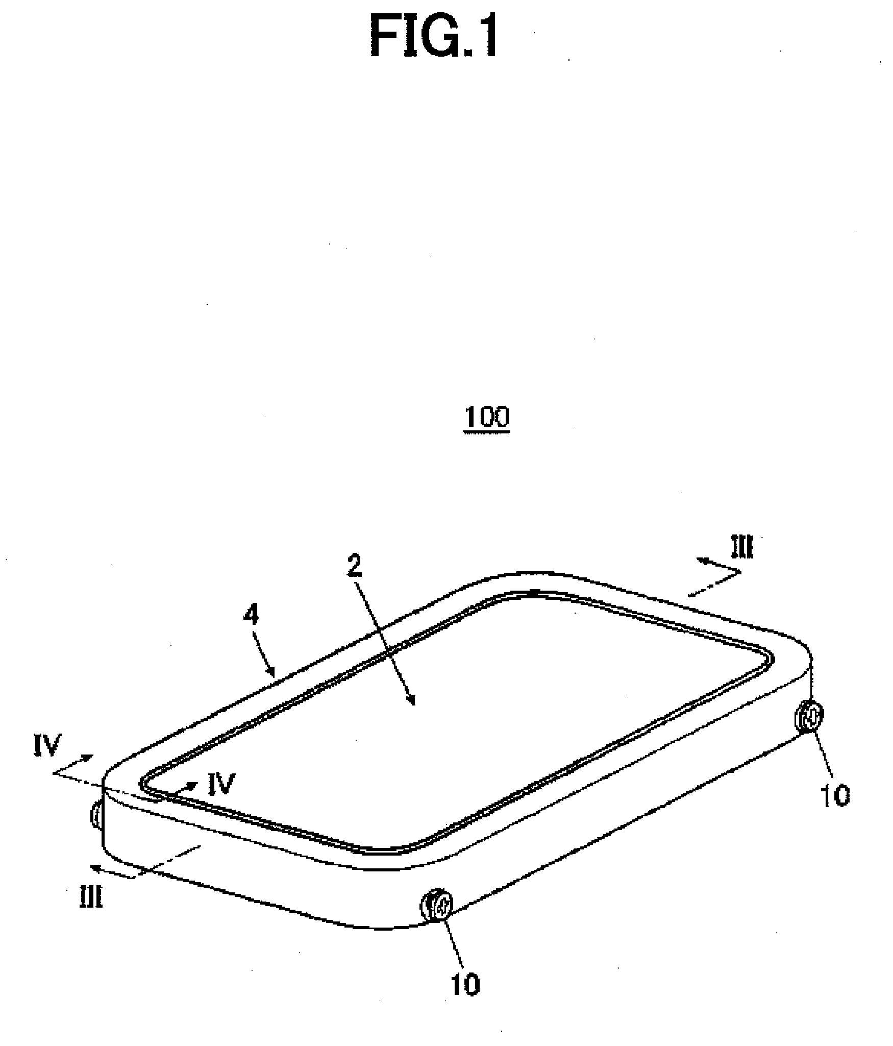
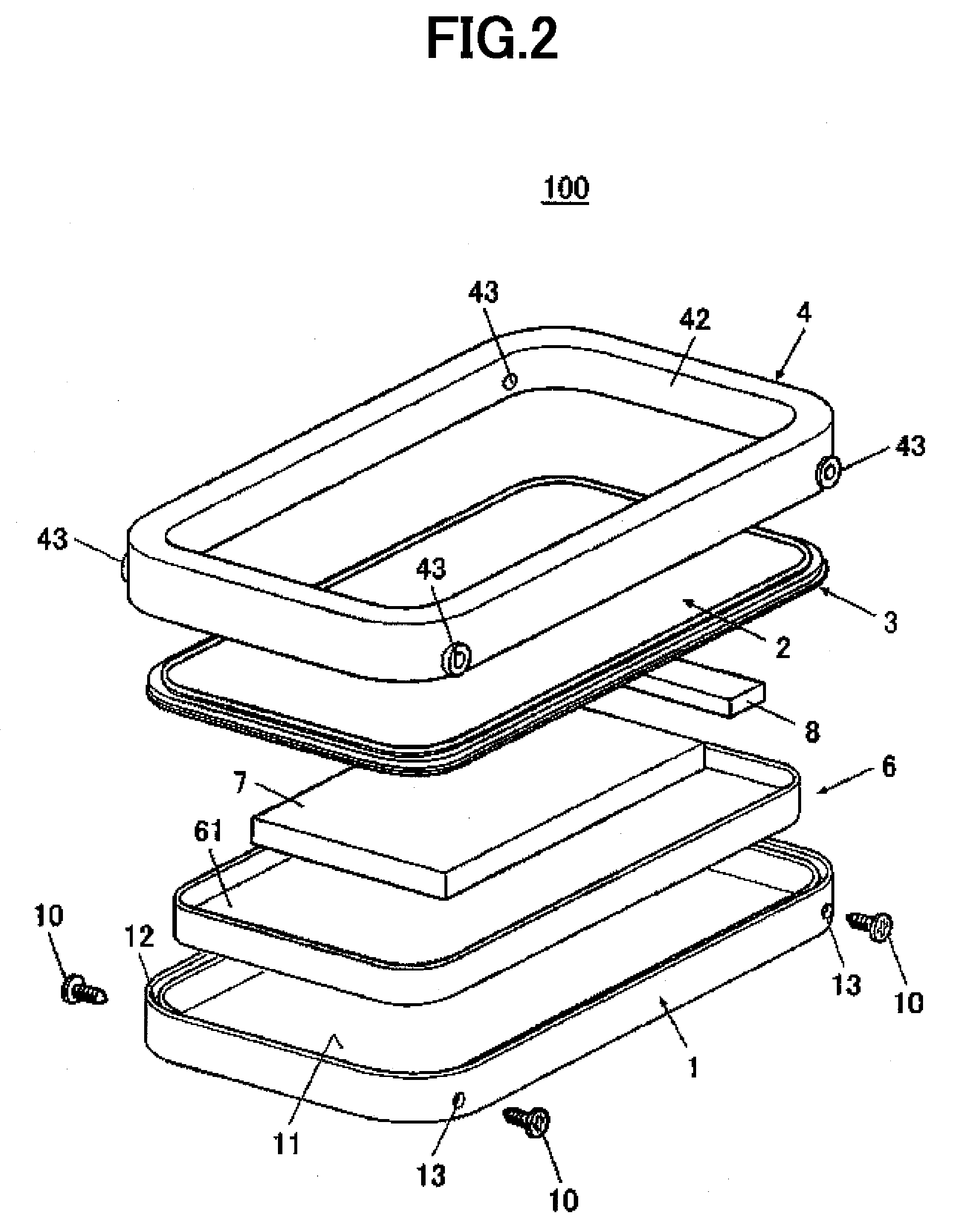
[0028]FIG. 1 is a perspective view of a display-side casing 100, FIG. 2 is an exploded perspective view of the display-side casing 100, FIG. 3 is an cross-sectional view in the direction of an arrow cut along cutting plane line III-III of FIG. 1, and FIG. 4 is a cross-sectional view in the direction of an arrow cut along cutting plane line IV-IV of FIG. 1.
[0029]In the following description, “vertical direction” is explained taking FIG. 3 as a reference.
[0030]A folding-type mobile telephone includes the display-side casing 100 and an operation unit casing. The display-side casing 100 has a display unit 7 including a liquid crystal display etc. A set of operation keys are provided at the operation unit casing. The display-side casing 100 and the operation unit casing are coupled by a hinge structure so as to be capable of rotation.
[0031]The display-side casing 100 includes a first case 1, a diaphragm 2, and a first resilient member 3. The first case 1 faces to the outside while the fo...
second embodiment
[0047]FIG. 5 is an exploded perspective view of the display-side casing 100A, and FIG. 6 is a cross-sectional view taken cut along a cutting plane line VI-VI with the display-side casing 100A in FIG. 5 assembled.
[0048]In the following description, “vertical direction” is explained taking FIG. 6 as a reference.
[0049]The second embodiment differs from the first embodiment in that the display-side casing 100A does not have a second case but rather a diaphragm 2A and a first case 1A are fixed directly.
[0050]Specifically, the display-side casing 100A includes the first case 1A, the diaphragm 2A, and a first resilient member 3A. The diaphragm 2A is provided facing the first case 1A and doubles as a display panel. The first resilient member 3A is formed integrally with a lower surface of the diaphragm 2A at a lower surface facing towards the side of the first case 1A.
[0051]The first case 1A has a recess 11A hollowed-out downwards as with the first case 1 of the first embodiment. The space ...
third embodiment
[0065]FIG. 7 is a perspective view of the display-side casing 100B. FIG. 8 is an exploded perspective view of the display-side casing 100B. FIG. 9 is a cross-sectional view in the direction of an arrow cut along cutting plane line IX-IX of FIG. 7. FIG. 10 is a cross-sectional view in the direction of an arrow cut along cutting plane line X-X of FIG. 7.
[0066]In the following description, “vertical direction” is explained taking FIG. 9 as a reference.
[0067]The third embodiment differs from the first embodiment in that a first resilient member 3B is fixed to the lower surface of a diaphragm 2B via a flexible wiring substrate 14B that is a film. The flexible wiring substrate 14B and the first resilient member 3B are integrally formed.
[0068]Specifically, the display-side casing 100B includes a first case 11B, the diaphragm 2B, and the first resilient member 3B. The diaphragm 2B is provided facing the first case 1B and doubles as a display panel. The first resilient member 3B is fixed to ...
PUM
 Abstract
Description
Claims
Application Information