Liquid Crystal Display Apparatus

a display device and liquid crystal technology, applied in the field of liquid crystal display devices, can solve the problems of complex circuit correction process, particularly prominent crosstalk caused by other source lines, etc., and achieve the effect of reducing the influence of crosstalk on the display screen, low correlation, and suppressing the influence of crosstalk

Inactive Publication Date: 2009-04-23
SHARP KK
View PDF10 Cites 26 Cited by
  • Summary
  • Abstract
  • Description
  • Claims
  • Application Information

AI Technical Summary

Benefits of technology

[0025]In other words, influence of the crosstalk is concentrated in the first display pixel, by treating three pixels including R, G, and B pixels as one unit in separation of display images with the use of a parallax barrier at the time when a dual view

Problems solved by technology

However, in a conventional arrangement, a circuit a process for correction become complicated.
In this du

Method used


Image

  • Liquid Crystal Display Apparatus
  • Liquid Crystal Display Apparatus
  • Liquid Crystal Display Apparatus

Examples


Embodiment Construction

[0038]One embodiment of the present invention is explained with reference to drawings.

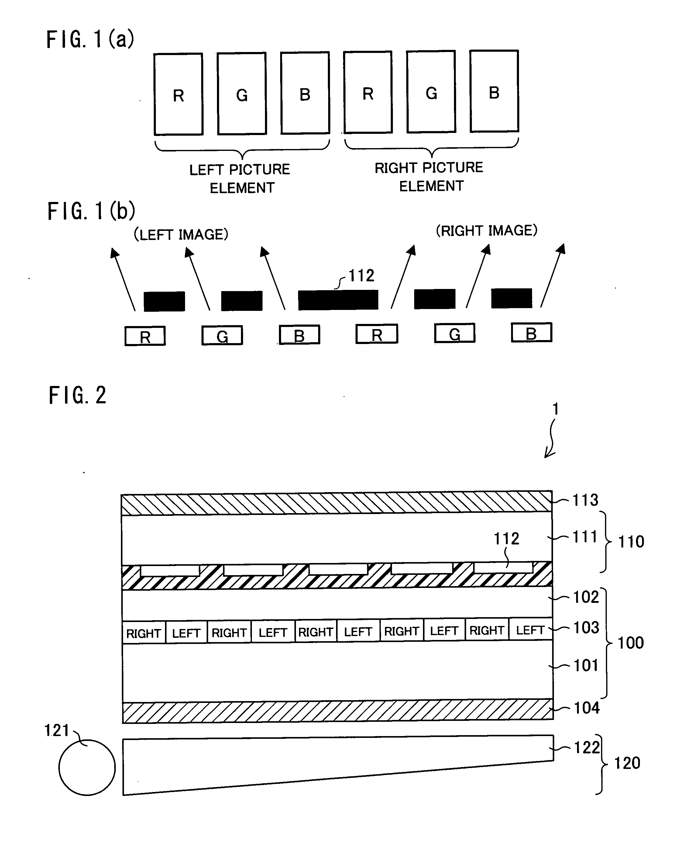
[0039]First, FIG. 2 schematically illustrates an arrangement of a liquid crystal display apparatus 1 of the present embodiment. The liquid crystal display apparatus 1 is a color liquid crystal display apparatus that is capable of performing a dual view display. As illustrated in FIG. 2, roughly, the liquid crystal display apparatus 1 includes a display panel 100, a parallax barrier 110, and a backlight 120.

[0040]The backlight 120 includes a light source 121 and a reflecting section 122. The reflecting section 122 reflects light that is emitted from the light source 121, so that light is irradiated on the display panel 100. Examples of the light source 121 are an LED (Light Emitting Diode), a CCFT (Cold Cathode Fluorescent Tube), and a CCFL (Cold Cathode Fluorescent Lump).

[0041]The display panel 100 is an active matrix type liquid crystal display panel in which a liquid crystal layer 103 made of a n...


PUM


Abstract

In a liquid crystal display apparatus realizing a dual view display by bonding a liquid crystal panel and a parallax barrier, the parallax barrier separates display images by treating three pixels including R, G, and B pixels as one unit (one picture element). At this time, luminance variation due to crosstalk concentrates on a right-end pixel among the three pixels constituting the one picture element (in a case where each pixel receives data from a source line immediately on the left of the pixel). Accordingly, the right-end pixel is arranged to be a B pixel that has a low correlation with luminance information and in which influence of crosstalk is hard to be viewed.

Description

TECHNICAL FIELD[0001]The present invention relates to a liquid crystal display apparatus that performs a dual view display, in particular, to a liquid crystal display apparatus that improves color reproducibility by reducing color crosstalk.BACKGROUND ART[0002]A problem of crosstalk is pointed out as a specific problem in a TFT-LCD. The crosstalk occurs because adjacent pixels are connected via a parasitic capacitance. In other words, when an insulating film intervenes between a transparent electrode and a source line, a parasitic capacitance is produced between the transparent electrode and the source line. In the same manner, parasitic capacitances are produced between a gate line and the transparent electrode and between the source line and a common electrode, respectively. Due to influence of these parasitic capacitances and a capacitance of a liquid crystal itself, an electric potential of a display pixel becomes different from a desired voltage when a gate is turned OFF. Conse...

Claims


Application Information

Patent Timeline
IPC IPC(8): G09G3/36
CPCG02F1/133512G02F2001/13606G09G2320/068G09G3/3648G09G2320/0209G09G3/003G02F1/13606
Inventor SHIOMI, MAKOTO
Owner SHARP KK
Why Eureka
Try Eureka