
Tdm/wdma passive optical network device

a passive optical network and optical network technology, applied in the direction of multimode transmission, fibre transmission, electrical apparatus, etc., can solve the problems of production cost increase, and achieve the effect of simplifying the transmission of downstream signals

Inactive Publication Date: 2009-04-23
ELECTRONICS & TELECOMM RES INST
View PDF5 Cites 34 Cited by
  • Summary
  • Abstract
  • Description
  • Claims
  • Application Information

AI Technical Summary

Benefits of technology

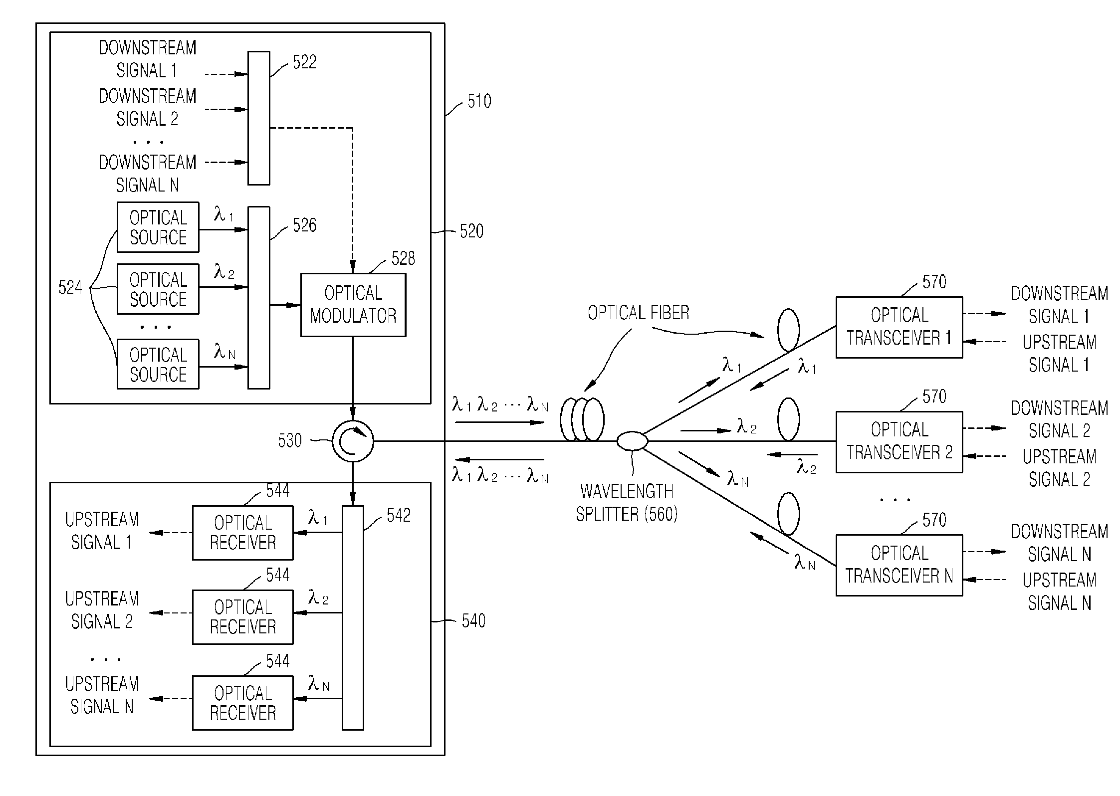
[0013]In order to make up for the disadvantages of a conventional TDM PON and a conventional WDM PON, the present invention provides a TDM / WDMA PON device in which a TDM scheme is applied to a downstream signal by reducing the number of optical transmitters, thereby simplifying transmission of a downstream signal such as a broadcast signal received by subscribers at the same time, and each subscriber uses an independent channel for a upstream signal by using a WDMA scheme, thereby sufficiently using the frequency band of an optical transceiver.

Problems solved by technology

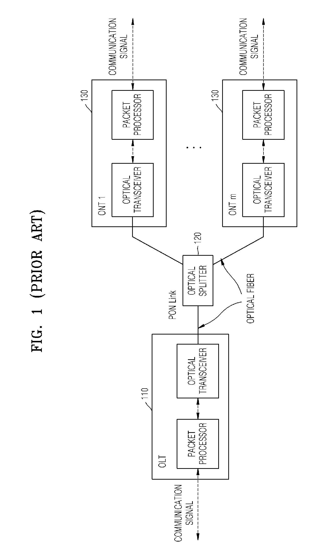
However, production costs increase because the numbers of optical transmitters 310 and optical receivers 360 of the OLT are the same as the number of subscribers, and the OLT has to repetitively transmit a downstream signal such as a broadcast signal at the same time to the subscribers because an optical splitter cannot perform transmission in a broadcast or multicast manner.

Method used


Image

  • Tdm/wdma passive optical network device
  • Tdm/wdma passive optical network device
  • Tdm/wdma passive optical network device

Examples


Embodiment Construction

[0022]Hereinafter, an embodiment of the present invention will be described in detail with reference to the accompanying drawings. It should be noted that like reference numerals refer to like elements illustrated in one or more of the drawings. In the following description of the present invention, detailed description of known functions and configurations incorporated herein will be omitted for conciseness and clarity.

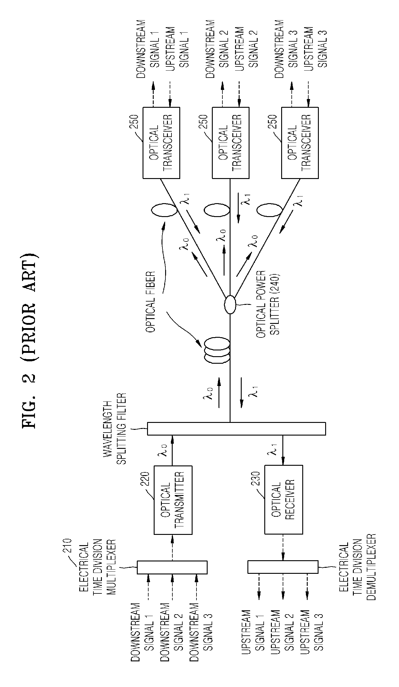
[0023]FIG. 4 is a block diagram illustrating a conventional time division multiplex (TDM) / wavelength division multiple access (WDMA) passive optical network (PON).

[0024]A technical issue to be addressed by the present invention for a TDM / WDMA PON is how to efficiently implement a TDM scheme and a WDMA scheme in the same optical network.

[0025]The conventional TDM scheme uses an optical power splitter 240 for splitting an optical signal for subscribers in an optical network. Since the optical power splitter 240 splits the power of an optical signal having a single wave...


PUM


Abstract

Provided is a time division multiplex (TDM) / wavelength division multiple access (WDMA) passive optical network (PON) device. The TDM / WDMA PON device comprises a base station terminal, a wavelength splitter, and a subscriber terminal optical transceiver. The base station terminal comprises a transmitter time-division-multiplexing and simultaneously modulating and outputting a plurality of different wavelength optical signals, an optical circulator transmitting the optical signals output from the transmitter to an optical distribution network and transmitting optical signals received from the optical distribution network to a receiver and the receiver demultiplexing wavelength division multiplexed upstream signals from the optical distribution network through the optical circulator, converting the demultiplexed upstream signals into a plurality of electrical signals, and delivering the electrical signals to an upper layer. The wavelength splitter splits the downstream signals from the base station terminal to subscriber ports corresponding to wavelengths and multiplexes the optical signals received from each of the subscriber ports to the base station terminal. The subscriber terminal-optical transceiver receives the downstream signals from the wavelength splitter and reuses the received downstream signals as optical sources for upstream signals.

Description

CROSS-REFERENCE TO RELATED PATENT APPLICATION[0001]This application claims the benefit of Korean Patent Application No. 10-2007-0105754, filed on Oct. 19, 2007, in the Korean Intellectual Property Office, the disclosure of which is incorporated herein in its entirety by reference.BACKGROUND OF THE INVENTION[0002]1. Field of the Invention[0003]The present invention relates to a passive optical network (PON) device for signal transmission between an optical line terminal (OLT) of a telephone office or a base station terminal and an optical network terminal (ONT) or an optical network unit (ONU) of a subscriber terminal in an optical subscriber network, and more particularly, to a time division multiplex (TDM) / wavelength division multiple access (WDMA) PON device in which data to be transmitted to each subscriber is multiplexed using a TDM scheme for transmission for downstream signals destined for an ONT / ONU from an OLT and signals to be transmitted from each subscriber are separately...

Claims


Application Information

Patent Timeline
Patent Type & Authority Applications(United States)
IPC IPC(8): H04J14/00H04B10/2581
CPCH04J14/0226H04J14/0227H04J14/0282H04Q11/0067H04Q2011/0016H04Q2011/0035H04J14/0252H04J14/0232H04J14/0238H04J14/0246H04J14/0247H04J14/025H04Q2011/0086H04B10/2581H04J14/00
Inventor LEE, DONG SOOYOON, BIN YEONGKIM, BONG TAE
Owner ELECTRONICS & TELECOMM RES INST
Learn More