
Synchronous optical bus providing communication between computer system components

a computer system and optical bus technology, applied in the direction of bus-type electromagnetic networks, electromagnetic network arrangements, electrical equipment, etc., can solve the problems of increasing the cost of the package, the power consumption of the processor, and the number of available pins, etc., and increasing the per pin speed. , the effect of increasing the power consumption

Active Publication Date: 2009-04-23
HEWLETT-PACKARD ENTERPRISE DEV LP
View PDF6 Cites 11 Cited by
  • Summary
  • Abstract
  • Description
  • Claims
  • Application Information

AI Technical Summary

Benefits of technology

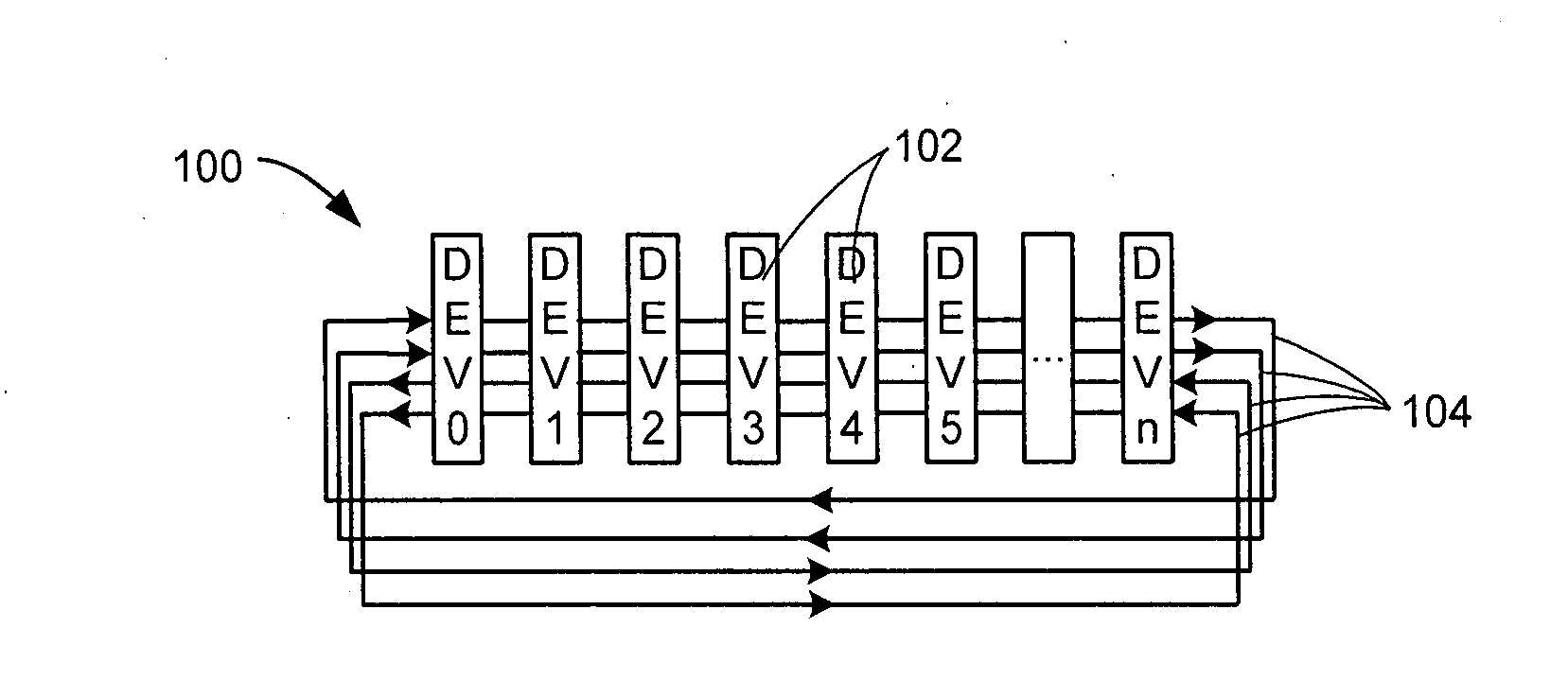
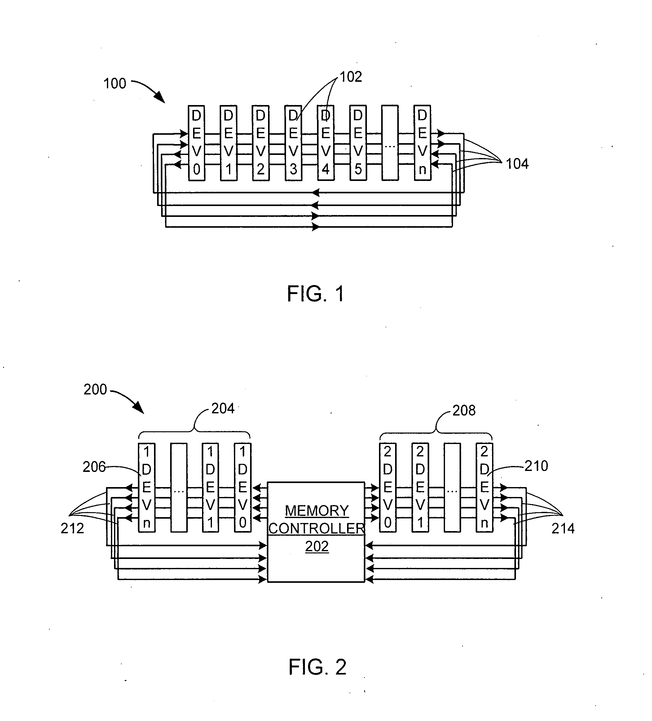
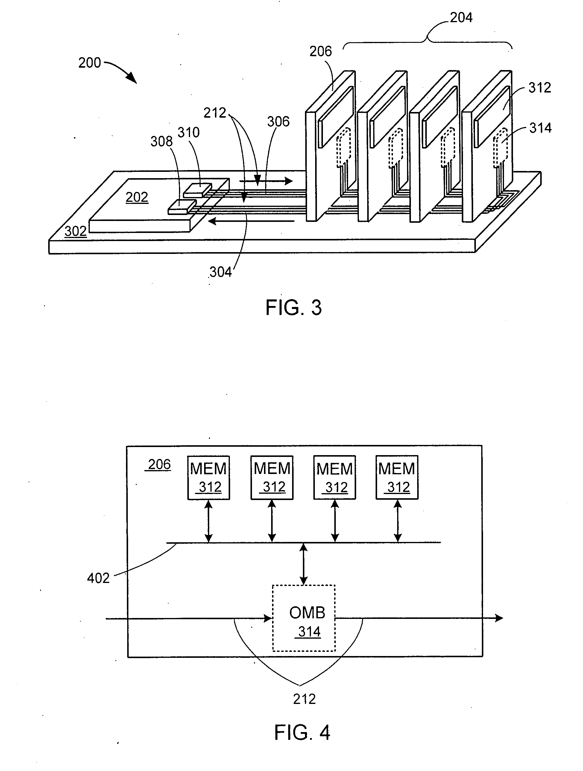
[0007]The present invention provides one or more embodiments of a synchronous optical bus system for providing communication between computer system components. The optical bus system comprises an optical interconnect which provides an optical data communication path for computer system components optically coupled to it. In one embodiment, each component is optically coupled via an optical bus interface unit to the optical interconnect, and the optical bus interface units are arranged on the optical interconnect in or

Problems solved by technology

Electrical communication architectures struggle to balance the dichotomy for increased performance required of electronic systems while addressing lower power consumption, smaller form factor, and lower electromagnetic emissions.
The number of available pins is not increasing substantially as this increases both the cost of the package, and the power consumption of the processor.
Increasing the per pin speed also increases power consumption.
At the same time the signal integrity problems of high speed electrical signalling mean that less memory devices can be put onto a memory bus as its speed increases.
Additional power is consumed since commands and data have to be retransmitted across multiple point to point hops.
However, this architecture does not scale well.
For example in a memory sub-system with point-to-point connections, the number of tranceivers and associated power dissipation would increase due to the increased number of optical interconnects needed to connect all the components.

Method used


Image

  • Synchronous optical bus providing communication between computer system components
  • Synchronous optical bus providing communication between computer system components
  • Synchronous optical bus providing communication between computer system components

Examples


Embodiment Construction

[0018]The following embodiments are described in sufficient detail to enable those skilled in the art to make and use the invention. It is to be understood that other embodiments would be evident based on the present disclosure, and that system, process, or mechanical changes may be made without departing from the scope of the present invention.

[0019]In the following description, numerous specific details are given to provide a thorough understanding of the invention. However, it will be apparent that the invention may be practiced without these specific details. In order to avoid obscuring the present invention, some well-known circuits, system configurations, and process steps are not disclosed in detail. Likewise, the drawings showing embodiments of the system are semi-diagrammatic and not to scale and, particularly, some of the dimensions are for the clarity of presentation and are shown greatly exaggerated in the drawing FIGs. Generally, the invention can be operated in any ori...


PUM


Abstract

A synchronous optical bus system for communication between computer system components is described. In one example, the optical bus system is used for communication between a memory controller and memory devices optically coupled to an optical interconnect. Optical bus interface units couple the components to the optical interconnect and are arranged on the optical interconnect in order that a sum of an optical path length from a controller component to each computer system component and from each computer system component to the controller component is the same for all the coupled computer system components. A synchronous protocol is used for communication between the components.

Description

TECHNICAL FIELD[0001]The present invention relates generally to optical computer system buses, and more particularly to optical memory buses.BACKGROUND ART[0002]Electrical communication architectures struggle to balance the dichotomy for increased performance required of electronic systems while addressing lower power consumption, smaller form factor, and lower electromagnetic emissions. Better solutions dealing with address scalability while reducing power consumption in computer systems are desirable. A memory system is an example of a typical computer system in which such better solutions are desirable.[0003]The increasing speed of microprocessors requires a corresponding increase in memory bandwidth. The ability to increase available memory bandwidth is constrained by two factors; the number of signal pins available on the processor package; and the speed at which these pins can be driven. The number of available pins is not increasing substantially as this increases both the co...

Claims


Application Information

Patent Timeline
IPC IPC(8): H04B10/00
CPCH04B10/801H04B10/278
Inventor BINKERT, NATHANJOUPPI, NORMSCHREIBER, ROBERTAHN, JUNG HOMCLAREN, MORAY
Owner HEWLETT-PACKARD ENTERPRISE DEV LP
Learn More