
Exposure Head, An Image Forming Apparatus and An Image Forming Method

an image forming apparatus and head technology, applied in the direction of electrographic process apparatus, optics, instruments, etc., can solve the problems of complicated emission switching timing control, difficult to increase the size of light emitting elements, so as to simplify the effect of emission switching timing control

Inactive Publication Date: 2009-04-23
SEIKO EPSON CORP
View PDF6 Cites 11 Cited by
  • Summary
  • Abstract
  • Description
  • Claims
  • Application Information

AI Technical Summary

Benefits of technology

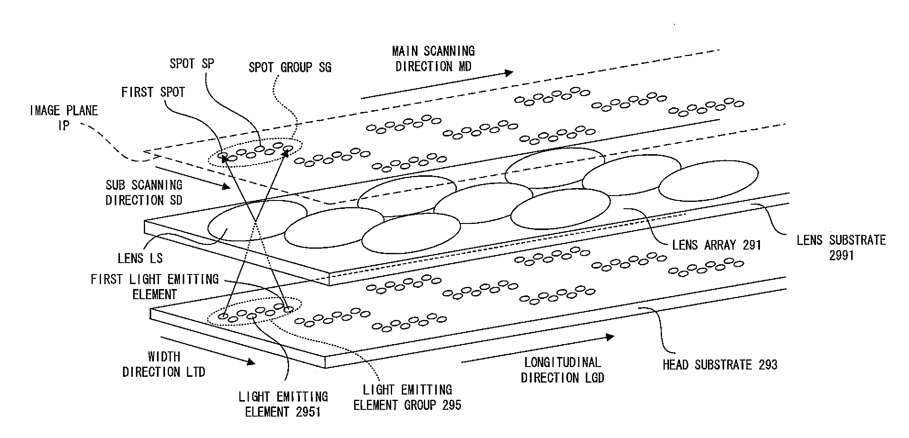
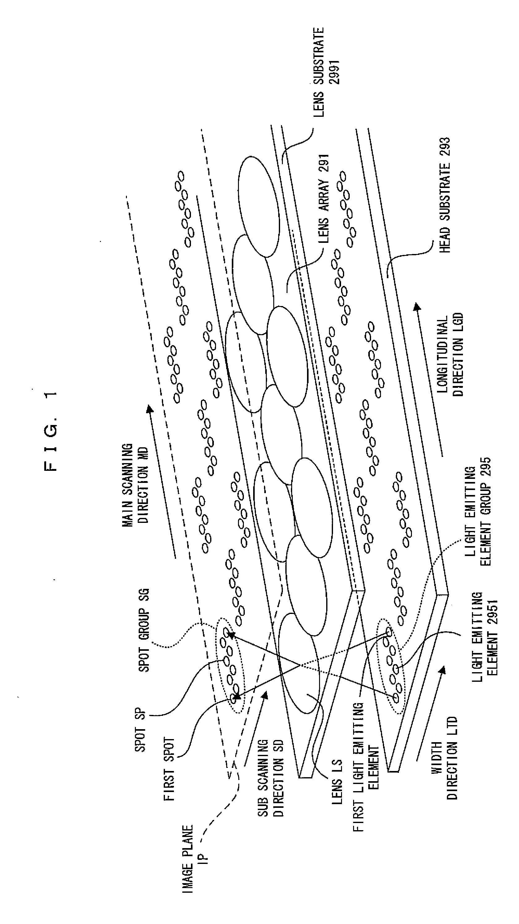
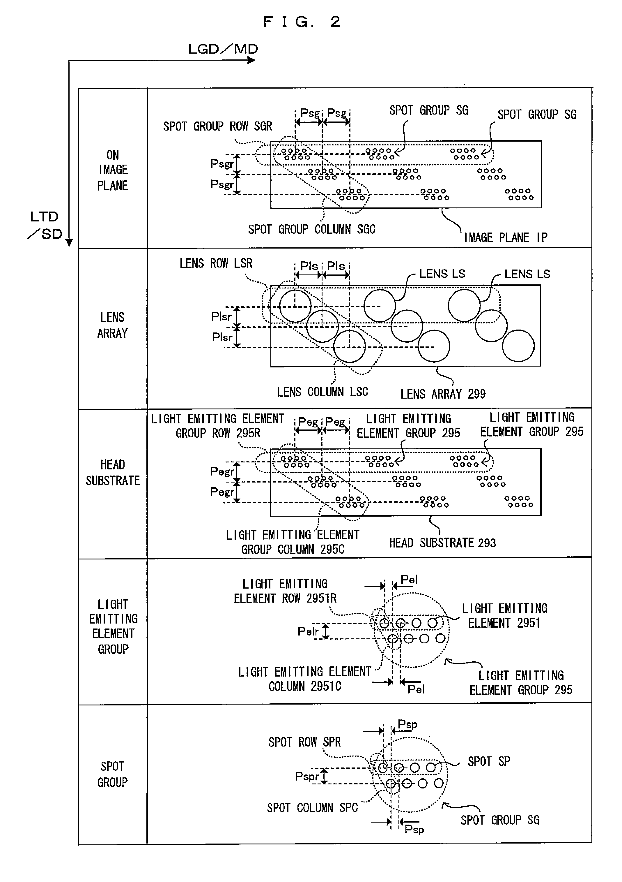
[0007]Accordingly, in order to easily realize better spot latent image formation, an exposure head having the following construction can be used. In this exposure head, light emitting elements are grouped into light emitting element groups. In addition, light emitting element groups are displaced from each other in a direction (width direction of the exposure head) corresponding to the sub scanning direction. By displacing the light emitting element groups in the width direction in this way, it becomes possible to easily increase the size of the light emitting elements and to realize good spot latent image formation.
[0010]An advantage of some aspects of the invention is to provide technology enabling the application of a common light emission switching timing control to light emitting element groups displaced from each other in a width direction and the realization of simplifying an emission switching timing control.

Problems solved by technology

However, in the above construction in which the light emitting elements corresponding to one line are arranged, it is not easy to increase the size of the light emitting elements.
This is because of a possibility of producing interference between adjacent light emitting elements in the case of making the light emitting elements larger.
Even more, as in the case where a pitch between light emitting elements is made smaller for higher resolution, it is even more difficult to increase the size of the light emitting elements.
As a result, there has been a problem of complicating an emission switching timing control.

Method used


Image

  • Exposure Head, An Image Forming Apparatus and An Image Forming Method
  • Exposure Head, An Image Forming Apparatus and An Image Forming Method
  • Exposure Head, An Image Forming Apparatus and An Image Forming Method

Examples


first embodiment

B. First Embodiment

[0050]FIG. 3 is a diagram showing an embodiment of an image forming apparatus to which the invention is applicable. FIG. 4 is a diagram showing the electrical construction of the image forming apparatus of FIG. 3. This apparatus is an image forming apparatus that can selectively execute a color mode for forming a color image by superimposing four color toners of black (K), cyan (C), magenta (M) and yellow (Y) and a monochromatic mode for forming a monochromatic image using only black (K) toner. FIG. 3 is a diagram corresponding to the execution of the color mode. In this image forming apparatus, when an image formation command is given from an external apparatus such as a host computer to a main controller MC having a CPU and memories, the main controller MC feeds a control signal and the like to an engine controller EC and feeds video data VD corresponding to the image formation command to a head controller HC. This head controller HC controls line heads 29 of th...


PUM


Abstract

An image forming apparatus, includes: a latent image carrier that moves in a moving direction; and an exposure head that includes a light emitting element which emits a light and an imaging optical system which images the light emitted from the light emitting element, and is adapted to form a spot on the latent image carrier, wherein a pitch in the moving direction of the latent image carrier between the spots formed by the different imaging optical systems is an integral multiple of a pixel pitch in the moving direction of the latent image carrier.

Description

CROSS REFERENCE TO RELATED APPLICATION[0001]The disclosure of Japanese Patent Applications No. 2007-271676 filed on Oct. 18, 2007 and No. 2008-218169 filed on Aug. 27, 2008 including specification, drawings and claims is incorporated herein by reference in its entirety.BACKGROUND[0002]1. Technical Field[0003]The invention relates to an exposure head for imaging light beams emitted from a light emitting element by an imaging optical system, and an image forming apparatus using the exposure head and an image forming method.[0004]2. Related Art[0005]An exposure head for imaging light beams emitted from light emitting elements as spots is known as such an exposure head. For example, in an exposure head disclosed in JP-A-2004-66758, a number of light emitting elements corresponding to one line are arranged in a direction corresponding to a main scanning direction and light beams emitted from the respective light emitting elements are imaged as spots by gradient index lenses. Latent image...

Claims


Application Information

Patent Timeline
Patent Type & Authority Applications(United States)
IPC IPC(8): G03G15/04
CPCG03G15/326G03G15/04072G03G2215/0412
Inventor INOUE, NOZOMUNOMURA, YUJIRO
Owner SEIKO EPSON CORP
Learn More