

Lancing device end cap with pressure-actuated surface features
Patent Information
- Authority / Receiving Office
- US · United States
- Current Assignee / Owner
- Publication Date
- 2009-04-23
- Estimated Expiration
- Not applicable · inactive patent
Smart Images
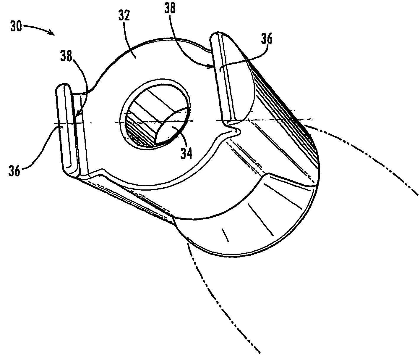
Figure 1 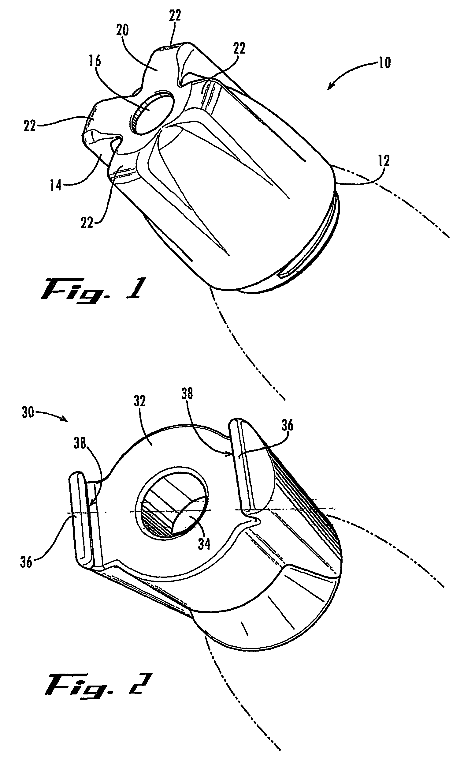
Figure 2 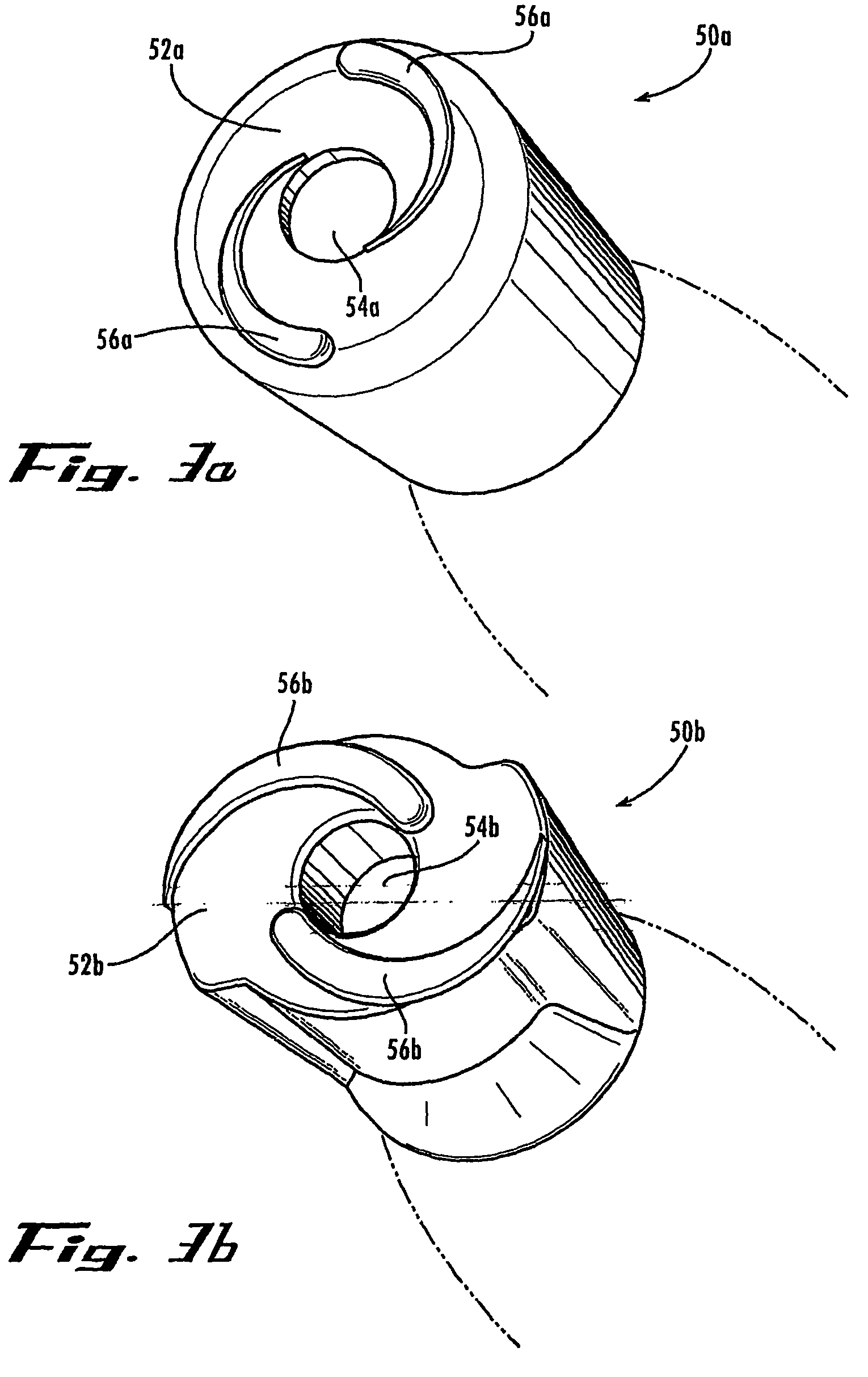
Figure 3
Abstract
Description
CROSS-REFERENCE TO RELATED APPLICATION
[0001] This application claims the benefit of U.S. Provisional Patent Application Ser. No. 60 / 503,862, filed Sep. 18, 2003, the entirety of which is hereby incorporated herein by reference for all purposes.TECHNICAL FIELD
[0002] The present invention relates generally to medical devices and procedures, and more particularly to lancing devices for sampling blood or other bodily fluids. The invention more particularly relates to an end cap for use in conjunction with a lancing device that allows for the collection of an increased volume of blood or bodily fluid to be sampled.BACKGROUND OF THE INVENTION
[0003] Many medical procedures require puncturing of the skin, and sometimes underlying tissues, of a human or animal subject. For example, a sharp lancet tip is commonly used to puncture the subject's skin for sampling of blood or other body fluid, as for example in blood glucose monitoring by diabetics. Generally, lancet blades or needles are much thin...
Examples
Embodiment Construction
[0017]The present invention may be understood more readily by reference to the following detailed description of the invention taken in connection with the accompanying drawing figures, which form a part of this disclosure. It is to be understood that this invention is not limited to the specific devices, methods, conditions or parameters described and / or shown herein, and that the terminology used herein is for the purpose of describing particular embodiments by way of example only and is not intended to be limiting of the claimed invention. Also, as used in the specification including the appended claims, the singular forms “a,”“an,” and “the” include the plural, and reference to a particular numerical value includes at least that particular value, unless the context clearly dictates otherwise. Ranges may be expressed herein as from “about” or “approximately” one particular value and / or to “about” or “approximately” another particular value. When such a range is expressed, another...