
Safety device for a liquid injection syringe, and a syringe assembly including the device

Active Publication Date: 2009-04-23
NEMERA LA VERPILLIERE SAS
View PDF36 Cites 59 Cited by
  • Summary
  • Abstract
  • Description
  • Claims
  • Application Information

AI Technical Summary

Benefits of technology

[0025]Indeed, assume that a closure plug for the syringe is screwed onto the fastener endpiece. By means of the pawl, the fastener endpiece is prevented from rotating relative to the syringe support, either even before a user begins to unscrew the plug, or else after the plug has started to be unscrewed over a short stroke. Furthermore, since the second complementary anti-rotation means constrain the syringe support in rotation with the sheath, the fastener endpiece is consequently, by transitivity, prevented from turning relative to the sheath. Thus, a user taking hold of the sheath can easily unscrew the plug carried by the fastener endpiece and then screw a needle carrier onto said fastener endpiece, without those screwing and unscrewing operations being impeded by unwanted turning of the fastener endpiece.
[0034]the device includes third complementary anti-rotation means for constraining the support and the sheath in rotation relative to each other about their axes, these third means being activated at least during axial displacement of the sheath and the support relative to each other from the disengaged position of the syringe needle towards the retracted position of said needle. These third means serve in particular to prevent the support from turning relative to the sheath while a spring is relaxing.

Problems solved by technology

Unfortunately, after the syringe has been mounted in the safety device, the fastener endpiece is generally rendered practically inaccessible by the protective endpiece that covers it.
The user therefore cannot act directly on the fastener endpiece to prevent it from turning, in particular while unscrewing the plug or screwing on the needle carrier.

Method used


Image

  • Safety device for a liquid injection syringe, and a syringe assembly including the device
  • Safety device for a liquid injection syringe, and a syringe assembly including the device
  • Safety device for a liquid injection syringe, and a syringe assembly including the device

Examples


Embodiment Construction

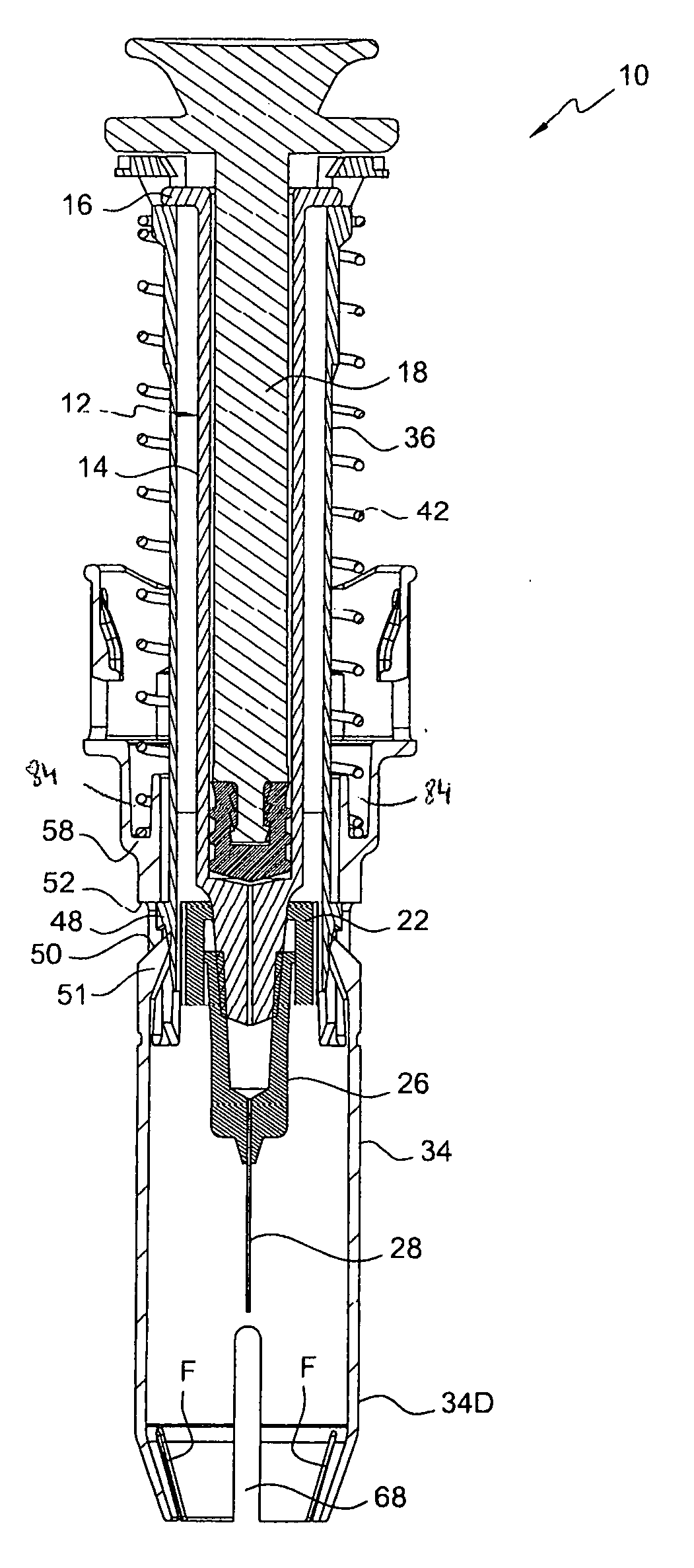
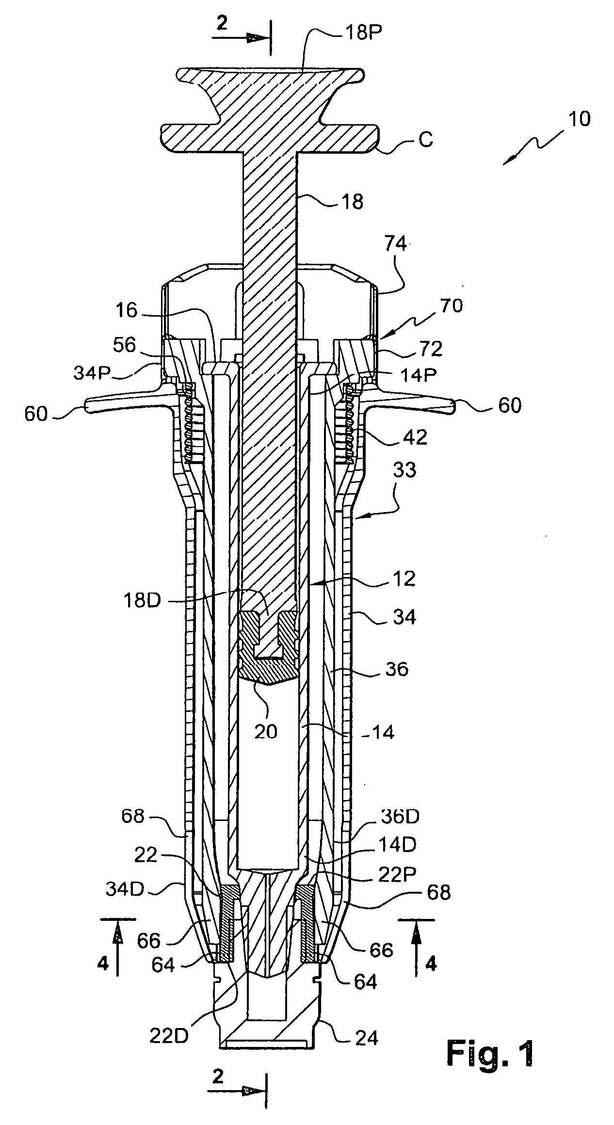
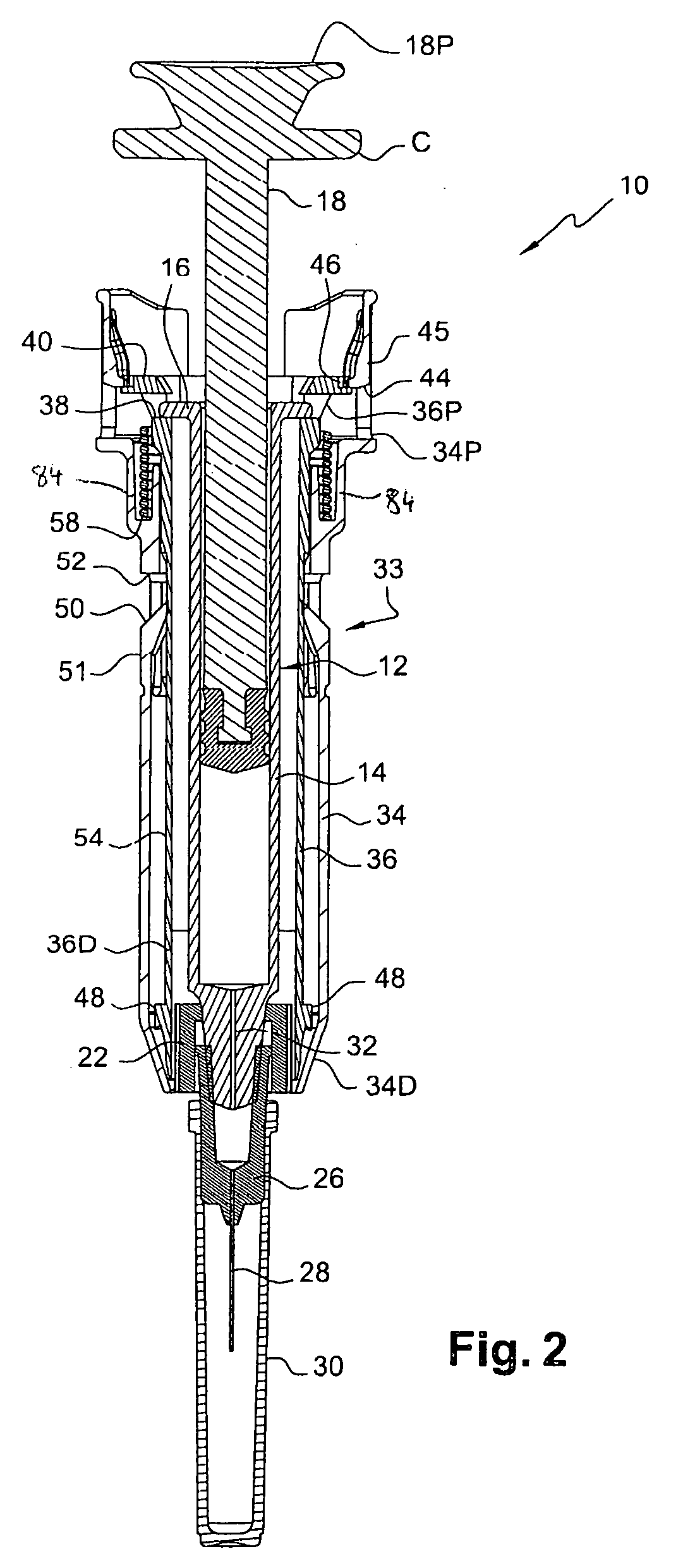
[0040]FIGS. 1 to 3 show a syringe assembly of the invention, given overall reference 10.

[0041]The assembly 10 comprises a conventional syringe 12 for injecting a liquid, in particular a medical liquid.

[0042]The syringe 12 has a tubular syringe body 14 forming a reservoir for the liquid. The body 14 has an open proximal end 14P provided with a collar 16, and a distal end 14D that is generally in the form of a cone converging away from the proximal end 14P.

[0043]The syringe 12 also includes a plunger 18 mounted to move axially in the body 14 between a ready position as shown in FIGS. 1 and 2 and a position at the end of injecting liquid, as shown in FIG. 3.

[0044]The plunger 18, e.g. made of plastics material, has a proximal end 18P outside the body 14, and a distal end 18D inside the body 14 and carrying a conventional piston 20. The proximal end 18P of the plunger forms a plunger drive end.

[0045]The syringe 12 also has an endpiece 22 for fastening a syringe closure plug 24, as shown ...


PUM


Abstract

The syringe comprises a body containing the liquid and having fitted thereto an endpiece for fastening a needle carrier. The safety device comprises a protective sheath and a syringe support that is received inside the sheath. The sheath and the support are axially movable relative to each other between two positions, namely a disengaged position of the needle, and a retracted position of said needle. The support includes anti-rotation means for constraining it in rotation about its axis and comprising at least one pawl urged resiliently into a position in which the pawl is designed to co-operate with complementary anti-rotation means of the fastener endpiece. The sheath and the support include complementary anti-rotation means for constraining them in rotation relative to each other about their axes and activated at least when the sheath and the support are in their disengaged position of the needle.

Description

FIELD OF THE INVENTION[0001]The present invention relates to the field of a safety device for a liquid injection syringe, in particular for a prefilled syringe.BACKGROUND OF THE INVENTION[0002]In the prior art, and in particular from WO 2006 / 050304, a liquid injection syringe is known of the type that comprises a body of generally tubular shape forming a reservoir for the liquid and having fitted thereto an endpiece of generally annular shape for fastening a needle carrier on the syringe body.[0003]The fastener endpiece is sometimes referred to as a “luer lock” and the needle carrier is sometimes referred to as a “luer needle”.[0004]The syringe also includes a plunger mounted to be movable axially in the body between a ready position and an end-of-liquid-injection position.[0005]Below, an element is said to be “proximal” or “distal” depending on whether it is axially close to or far away from the end of the plunger that is to be actuated by a user.[0006]WO 2006 / 050304 also describes...

Claims


Application Information

Patent Timeline
IPC IPC(8): A61M5/32
CPCA61M5/3129A61M5/3202A61M5/326A61M5/3271A61M2005/3264A61M5/347A61M2005/3104A61M2005/3247A61M2005/3261A61M5/344
Inventor BRAND, JULIENDUGAND, PASCALLANZI, SYLVAINRIMLINGER, THIERRY
Owner NEMERA LA VERPILLIERE SAS
Learn More