Handle for stepwise deployment

a technology of stepwise deployment and handle, which is applied in the field of implantable delivery or deployment system to achieve the effect of reducing the effective diameter of the delivery system and greater control

Inactive Publication Date: 2009-04-23
ABBOTT LAB VASCULAR ENTERPRISE
View PDF22 Cites 43 Cited by
  • Summary
  • Abstract
  • Description
  • Claims
  • Application Information

AI Technical Summary

Benefits of technology

[0005]An elongate gear rod defining a plurality of serrations, is provided, each serration being of equal length, the gear rod being attached to the slide member. An activation element, or button, is pivotally connected to the base member, and a driving element extends from the activation element. Under this configuration, pivotal depression of the activation element causes the driving element to engage one of the serrations on the gear rod and to move the gear rod proximally in relation to the base member, thereby incrementally retracting the sheath from the prosthesis. In an important aspect of the invention, the activation element is dimensionally configured in relation to the base member and the gear rod so that proximal movement of the gear rod caused by a single depression of the activation element cannot exceed the length of a single serration. This structure has the advantage of permitting movement of the sheath in relation to the catheter of only a predetermined small amount for each depression of the activation element. This provides for greater control, and will not allow accidental hand moveme

Problems solved by technology

This provides for greater control, and will not allow accidental hand movemen

Method used


Image

  • Handle for stepwise deployment
  • Handle for stepwise deployment
  • Handle for stepwise deployment

Examples


Embodiment Construction

[0019]With reference to the drawings, which are provided by way of exemplification and not limitation, there is described an apparatus for controlled stent delivery having features of the present invention.

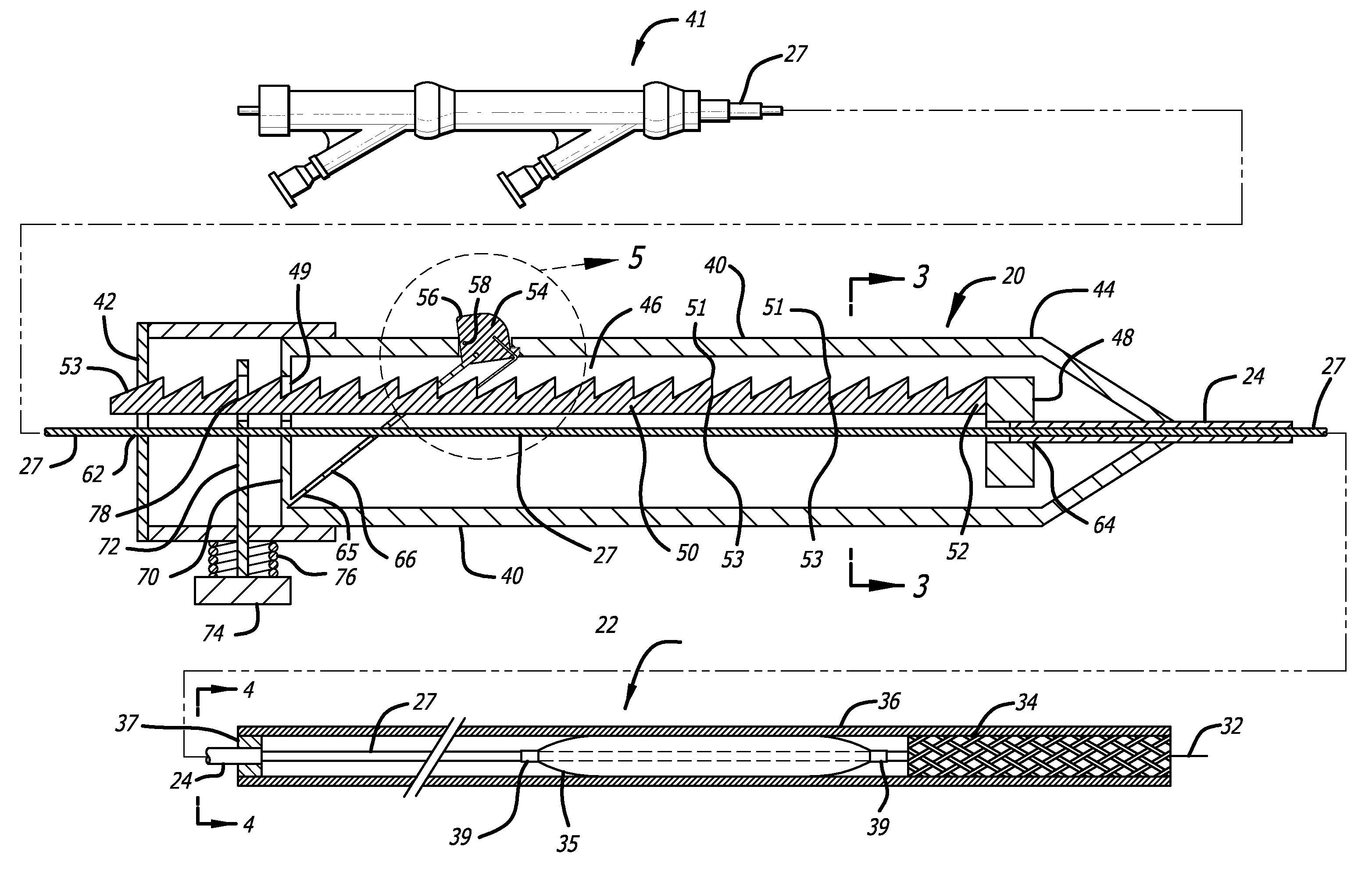
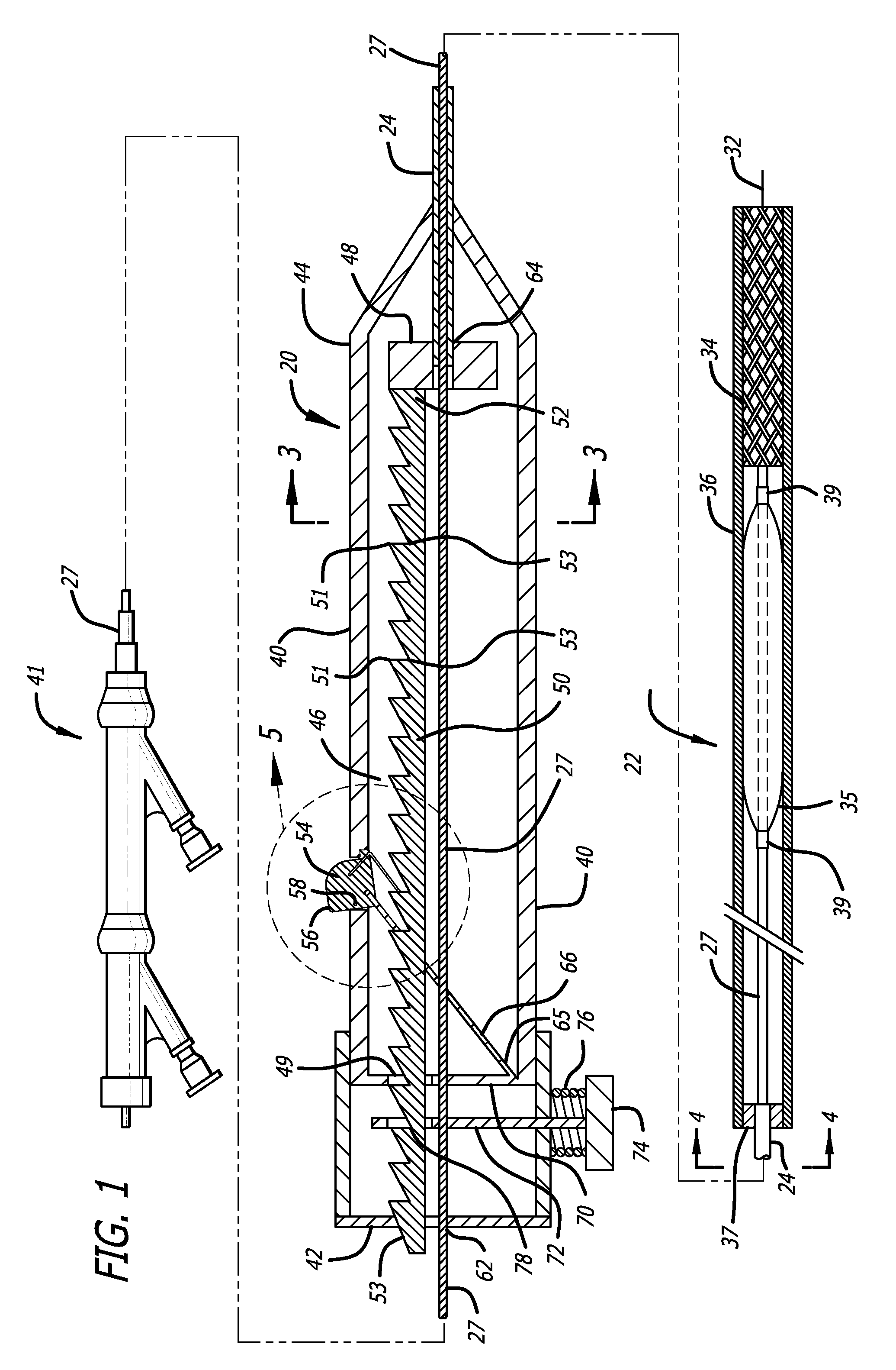
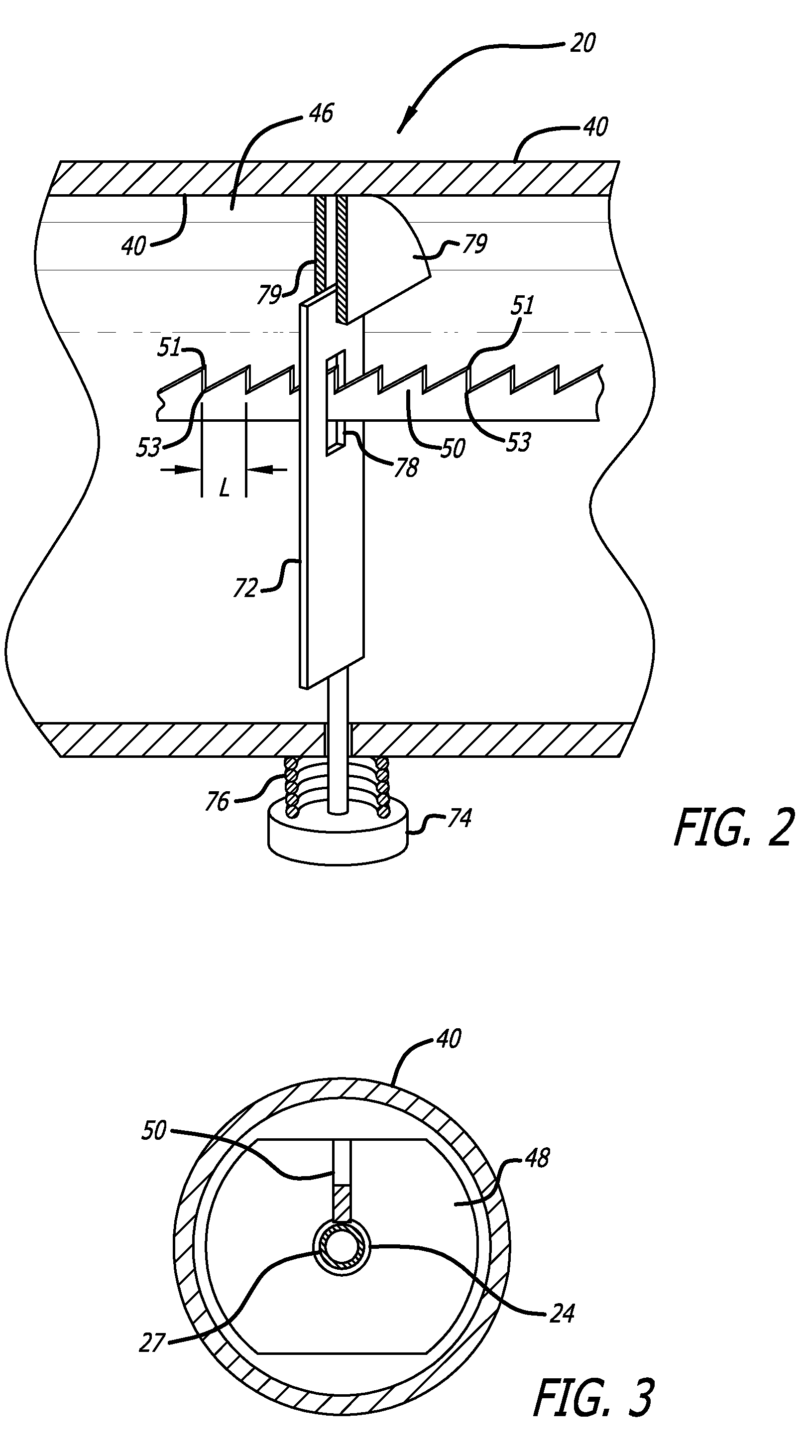
[0020]A preferred embodiment of the invention includes a release handle, generally identified by the numeral 20. (FIG. 1.) The release handle is adapted to operate in conjunction with a catheter 22. The catheter is configured to remotely deliver a prosthesis in a body vessel or duct.

[0021]Catheters for remotely delivering a prosthesis are known, and may include a core cylinder 27 having an internal lumen 28. (FIG. 4.) A guidewire 32 may be inserted within the lumen 28, according to known usage wherein the guidewire is first threaded into a body vessel (not shown), whereafter the catheter 22 is run up into the body vessel over the guidewire 32. At the distal end of the catheter, a prosthesis may be positioned to surround the catheter. In FIG. 1 it is shown that the prosthesis may b...


PUM


Abstract

A system for controlled deployment of a prosthesis, in which a sheath is retracted from a prosthesis in a body vessel or duct. The system includes a handle for deploying the prosthesis, the handle comprises a base member fixed to a catheter, and a slide member for sliding past the base member, the slide member being fixed to an end of a retraction member. The slide member includes a serrated gear rod, and the handle is configured such that, when activated, the gear rod moves in relation to the base member by no more nor less than the length of one serration on the gear rod.

Description

BACKGROUND OF THE INVENTION[0001]The present invention relates to an implant delivery or deployment system. More specifically, the invention relates to a deployment system that uses a handle operable under automatically controlled conditions to retract the retractable outer sheath and deploy a medical implant for minimally invasive application, such as an endovascular stent graft, vena cava filter, self-expanding stent, balloon expandable stent, angioplasty balloon, and the like.[0002]Delivery systems for deploying a medical implant, such as an endovascular stent graft, vena cava filter, self-expanding stent, balloon expandable stent or the like, are known in the field of medical technology. These medical devices have many uses and applications. In particular, a stent is a prosthesis or implant which is generally tubular with openings formed therein, and which is expanded radially in a vessel or lumen to improve and reinforce the vessel's patency. Stents are widely used in body lume...

Claims


Application Information

Patent Timeline
IPC IPC(8): A61F2/06
CPCA61F2002/9517A61F2/95A61F2/9517
Inventor KOCH, INA
Owner ABBOTT LAB VASCULAR ENTERPRISE
Why Eureka
Try Eureka