Cooling Storage Cabinet and Method of Operating the Same

a storage cabinet and cooling technology, applied in the direction of domestic cooling apparatus, static/dynamic balance measurement, instruments, etc., can solve the problems of difficult absorption of heat by the evaporator, reduced cooling performance, and dissipation of heat from the condenser, so as to achieve the effect of stably controlling the internal temperature drop over time and easy realization

Inactive Publication Date: 2009-04-23
HOSHIZAKI ELECTRIC CO LTD
View PDF18 Cites 19 Cited by
  • Summary
  • Abstract
  • Description
  • Claims
  • Application Information

AI Technical Summary

Benefits of technology

[0017]In accordance with the present invention, control of the internal temperature drop over time can be stably performed. Furthermore, it is necessary only to change the setting of the rotational speed of the inverter compressor. Therefore, it can be easily realized.

Problems solved by technology

Here, if the condensing capacity such as the air volume of the condenser fan is not changed, dissipation of heat from the condenser is limited, and therefore absorption of heat by the evaporator is difficult.
As a result, the cooling performance becomes lower.
Thus, where the degree of increase and decrease in cooling performance between each of the stages is different depending on the level of the rotational speed of the inverter compressor, there is a concern that a too high or too low cooling performance results (as explained above) in the case of performing the control to increase or decrease the rotational speed of the inverter compressor stage by stage depending on whether the actual temperature drop rate is higher or lower than the target temperature drop rate, and, because of the too high or too low cooling speed, the control to drop the temperature according to the predetermined cooling characteristic cannot be stably executed.

Method used


Image

  • Cooling Storage Cabinet and Method of Operating the Same
  • Cooling Storage Cabinet and Method of Operating the Same
  • Cooling Storage Cabinet and Method of Operating the Same

Examples


first embodiment

[0036]A first embodiment in accordance with the present invention will be explained with reference to FIGS. 1 through 10.

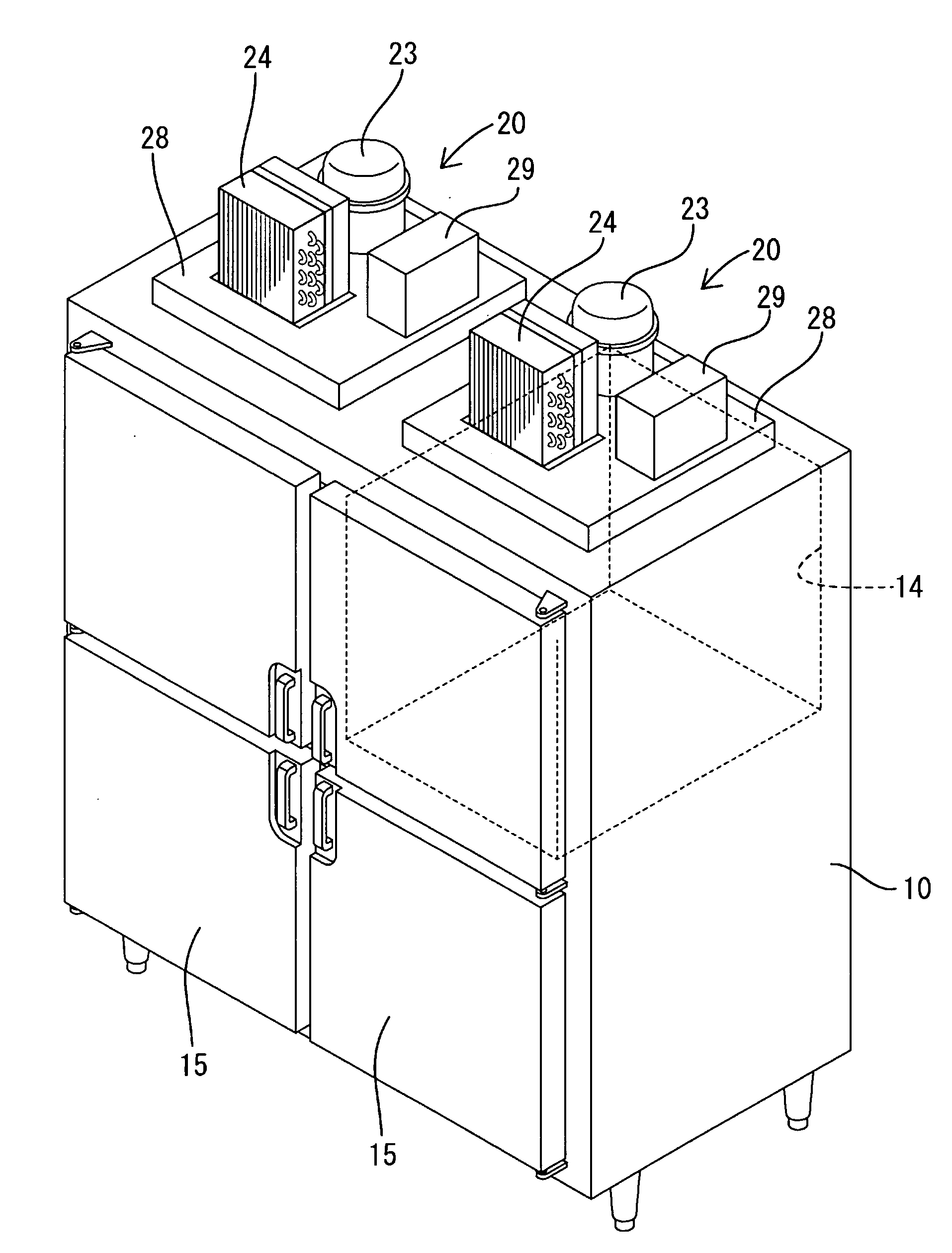
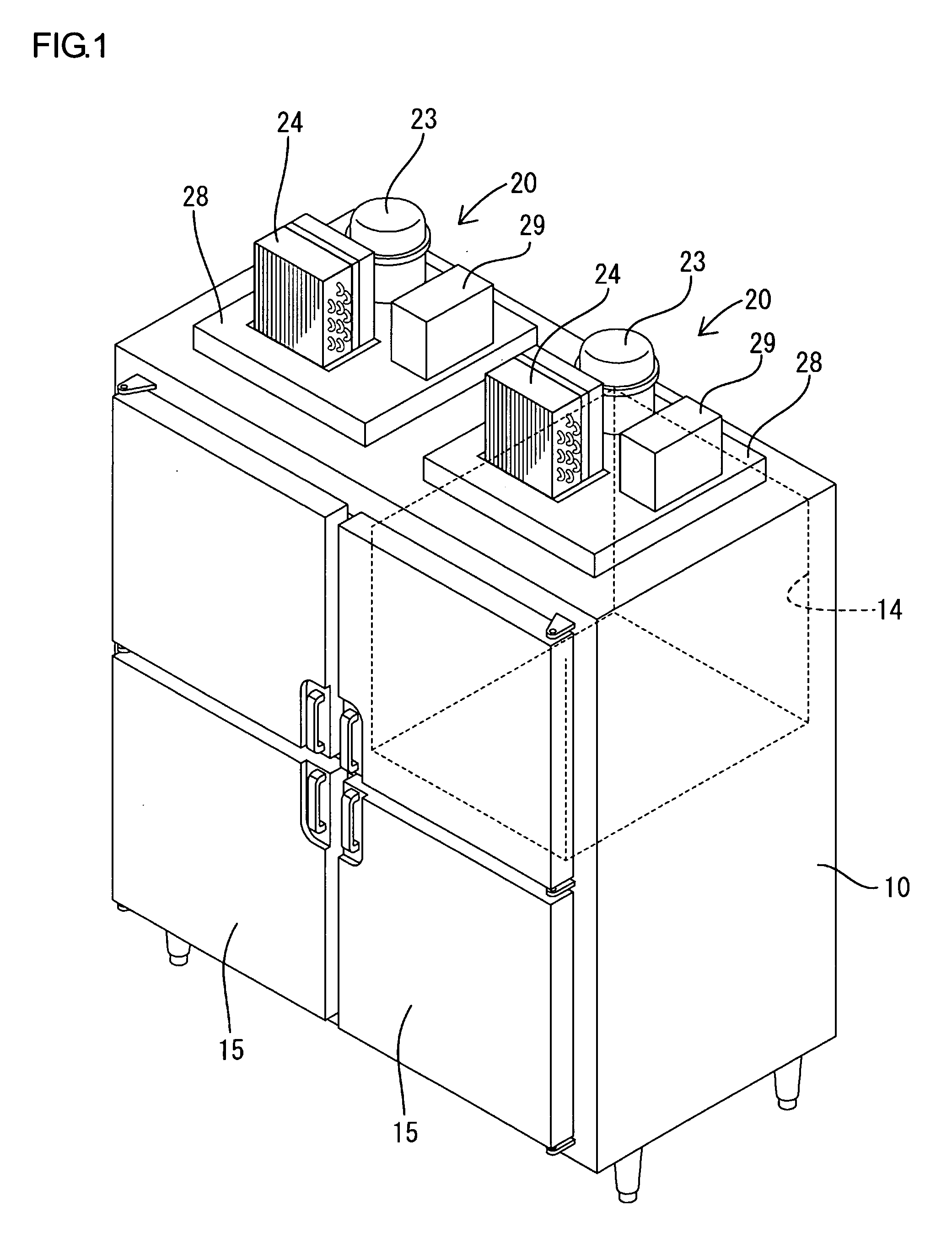
[0037]The freezer-refrigerator is of a four-door type and, as shown in FIG. 1, is provided with a body 10 including a heat-insulating box body having a front opening. The front opening is partitioned with a cruciate partition frame and thereby four openings 11 are defined. A substantially quarter inner space that corresponds to an upper right opening 11 as viewed from the front is partitioned with heat-insulating partition walls and thereby is arranged as a freezing compartment 14. The remaining three quarters areas are arranged as refrigerating compartments 13. Each of the openings 11 has a heat-insulating door 15 mounted thereto so as to pivotally open and close.

[0038]A machine compartment 18 is configured on the top of the body 10 by panels 17 (see FIG. 3) planted around the top of the body 10. The top of the body 10 serves as a bottom of the machine compartmen...

second embodiment

[0067]FIGS. 11 and 12 show a second embodiment of the present invention.

[0068]The difference from the first embodiment is that, as shown in FIG. 11, the ideal temperature curve in the control cooling is formed by a curve line xc1 of a quadratic function (T=f (t)) of temperature and time. As a whole, similar to the straight line xc of the first embodiment, a slow temperature drop is arranged. Note that, in the case of the quadratic function xc1, since the target temperature drop rate is not fixed but is varied depending on the internal temperature, a calculating section that calculates it is provided. More specifically, in the calculating section, at every predetermined sampling time, a target temperature drop rate Ac1 is calculated from the quadratic function xc1 as a temperature drop amount per unit time (AT / At) at the internal temperature (at that moment), and is outputted. Note that the temperature drop rate Ac1 may be found as a differential (dT / dt) of the quadratic function xc1...

third embodiment

[0073]FIGS. 13 through 15 show a third embodiment in accordance with the present invention. In the third embodiment, based on the ideal pull-down-cooling characteristic, a target temperature drop rate Ap2 that corresponds to the internal temperature is calculated in advance and, as shown in FIG. 13, a reference table referring the internal temperature to the target temperature drop rate Ap2 is prepared in advance. In addition, based on the ideal control-cooling characteristic, a target temperature drop rate Ac2 is calculated in advance and, as shown in FIG. 14, a reference table referring the internal temperature to the target temperature drop rate Ac2 is prepared in advance. As the internal temperature in the reference table, the temperatures within a control-cooling zone is adopted. Both of the two reference tables are stored in the data storage section 43.

[0074]The others are similar to the first embodiment, including that the rotational speed of the inverter compressor 23 in eac...


PUM


Abstract

A cooling device is provided with an inverter compressor. Set speeds of the inverter compressor can be switched to six stages from a first speed to a sixth speed. The relationship between each of the set speeds of the rotational speed is set so that the stages adjacent to each other have gradually larger differences in rotational speed as the rotational speed becomes higher. With this, independently from the level of the rotational speed, a degree of increase in cooling performance between each of the stages can be equalized. In a case of performing a control to increase or decrease the rotational speed of the inverter compressor stage by stage depending whether an actual temperature drop rate is larger or smaller than a target temperature drop rate, the change amounts in cooling performance that can be substantially equalized, and too high or too low cooling performance does not result, i.e. fluctuation in cooling performance can be minimized. Thus, control to drop the internal temperature in accordance with a predetermined cooling characteristic can be stably performed.

Description

TECHNICAL FIELD[0001]The present invention relates to a cooling storage cabinet having an inverter compressor and an operating method thereof.BACKGROUND ART[0002]In recent years, refrigerators such as for commercial use and having inverter compressors have become widely used. The inverter compressor can perform speed control. By using the inverter compressor, there are many advantages, one of which is higher efficiency in performing control cooling. That is, in a case of performing control cooling to maintain an inside of the refrigerator around a set temperature, rotational speed (revolution number per unit time) of the inverter compressor is controlled to be reduced stage by stage in the vicinity of the set temperature. By adopting this control method, a continuous ON time of the compressor becomes much longer; in other words, the number of switching between ON and OFF is considerably reduced. Furthermore, the compressor is driven at lower rotation. Therefore, higher efficiency an...

Claims


Application Information

Patent Timeline
Patent Type & Authority Applications(United States)
IPC IPC(8): G05B15/00F25D11/00
CPCF25B49/025F25B2600/021Y02B30/741F25D2317/0665F25D2400/14F25D17/067F25D2317/0655Y02B30/70
Inventor KAGA, SHINICHIHIRANO, AKIHIKO
Owner HOSHIZAKI ELECTRIC CO LTD
Why Eureka
Try Eureka